Oh hello everybody! It’s a few days after Dragon Con and I’ve finally woken back up. Where the hell am I?! What is this metallic coating all over my face? Why have I gained 20 delicious pounds?
Here it is, the Post Dragon Con 2016 recap. I didn’t get a change to put out another update before leaving for Atlanta, and then it was a mad pre-convention dash. So this update will cover all of the construction of Roll Cake, as well as get started on the Bot that Charles Forgot – Überclocker 4.0, a.k.a “I Can’t Believe It’s Not Overhaul!”.
Amazingly enough, there were no van shenanigans on the way down. I’m staying in Atlanta a few days later again, so the return trip is still clouded in the ether, but at this time (Boston to Atlanta and now a few hundred miles locally) there are no issues to report.
Alright, I lied a little – at some point a few weeks (months???) ago, the rearmost portion of the exhaust pipe decided to fall off. It had a hanger at the very back of the frame, so did not fall completely off, but just rattled haplessly.

I think it was due to the bend passing over the rear axle being repeatedly struck by said axle when Mikuvan is loaded heavy – such as the trip to Detroit Maker Faire. So anyway, all it manifested in was things being a little louder, but at times due to the exhaust being trapped under the body and in my 3-mile-long wake vorticies, exhaust smell would creep into the cabin. This is not something I wanted to deal with for the long trip down, so I repaired in the best WEEABOO REDNECK way possible:

None of this BEER CAN bullshit… only the best Ramune bottles will be used for MY hoodrat repairs!
This held all the way until South Carolina. When I rolled into town, one of my pre-convention stops was the local Advance Auto Parts to pick up a patch pipe. The whole system is definitely in need of replacement, though. Who wants to hook me up with D U A L F L O W M A S T E R S?
Anyways, without further ado, here are the sections of this roman noir de robots:
- Finishing and testing Roll Cake
- Designing and building Überclocker 4
- Robot Battles and Dragon Con recap
Icing on the Roll Cake
So this is where we build up to that ‘preview picture’ I posted last time. One of the first things I did as soon as I put the frame pieces printing on the Mark Two was go and do basically the only machining thing, which was make the drum.

For this, I brought back an old friend. One of my first major tool purchases was this little indexing head, which made its first appearance here in a LOLioKart build report. It became my most prized possession for some time thereafter, but I left it in the shop when I mostly scuttled off to main campus and upstairs into the IDC for graduate school nonsense. With my departure, it began becoming decrepit under usage by random newbies. One of the dividing plates was lost, and one of the tilting locks was also lost after someone cranked the locking bolt too tight and sheared it off.
Every once in a while, someone does find it again and use it, so I knew it was still operational. I gave it a once-over cleanup and adjustment before starting here.
The drum blank was carved out on New MITERlathe before being transferred to the indexing head for feature drilling. I originally specified 6 bolt holes. But as it turns out, 8 holes is easier to use the indexer for, since it didn’t involve going in partial circles using the dividing plates. Just 5 cranks of the handle… So, 8 holes it is.

Next up, putting the big 1/2″-13 threads in for the cap screw “teeth”.

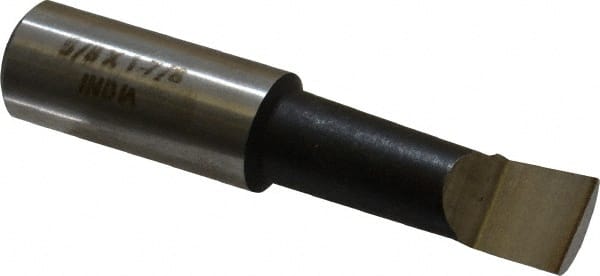
One tricky operation was broaching the 8mm bore for a 2mm keyway. Since Roll Cake is being built from Banebots P80 parts, so it must be compatible with an 8mm keyed shaft. I could not get a 8mm bushing & 2mm broach in time – nor did i want to spent dozens of dollars for the honor. So I did what, I guess, I would do, and carefully hacked at it with a 1/16″ endmill until I got a 2mm slot with a bit of radius at the end.
Precision! Craftsmanship! Finesse! We strive to be the opposite of this at Big Chuck’s Robot Warehouse. Zero sigmas, guaranteed, or I’m keeping your damn money anyway.

The frame parts have finished printing from the new Onyx material!
Well, hold up a little… These are extremely hollow prints that were solely to test for dimensional correctness. Things like “Does the motor fit in this hole?” and similar.

Here is a mock fit with some of the parts. I used a paint marker to pinpoint locations which needed rework – generally increasing slop or tolerances in the CAD model to get a better fit in real life.

Another arrangement of “DO NOT USE THESE FOR REAL” parts, which all had X marked on them so I was not tempted.

The two main frame halves are actually made from regular nylon for the most part, with carbon fiber loops in the center of the bot to strengthen the area. Otherwise, the regular nylon is tough and a bit flexible, which will hopefully help against some impacts.

A little pile of wheels with grommet-tires installed…

I next synthesized these planet gears from spare P80 4:1 and 3:1 planet gears. The 4:1 gears were bored out and cut to half a normal pinion length. Then the 3:1 gears were machined down for half their length, and then promptly shoved into the 4:1 hollow half-gears. The shoving first involved lining one tooth with one valley between teeth on each gear. As mentioned in the design post, these compound gears require the correct phasing of teeth to be assembled succesfully. I was probably off by some fractions of a degree on each gear.
THAT’S WHY WE HAVE A PLASTIC RING GEAR
The ring gear itself has also been reprinted in carbon fiber back Onyx (a material we came to call RMCC – Reinforced MarkForged Carbon-Carbon). I made the number of engagement dogs lower to guarantee the servo being able to reach between them.

Assembly for realsies begins with the bolting together of the sides. On each side, three #4-40 cap screws with washers and nuts retain the sides to the center U, and at the very rear, a #4-40 threaded rod with 4 nuts provides last-ditch backup if those front fasteners fail.

The ‘flaps’ are waterjet-cut 6061 aluminum 1/16″ thick sheet, which are bent up at the edges like so:

Well, that’s how it’s supposed to work. I really need to watch some tutorials on how to use a box-and-pan metal brake correctly, because I clearly can’t do so, ever – and it probably doesn’t help that I make sheet metal parts infrequently enough that the shared machinery is never in the same condition twice (or some times working at all), so I have no clue how it’s supposed to behave. Anyways, no two bends on this thing are alike in location and alignment. One side is workable, the other side is very twisted… Oh well, we’ll fix it in post.

Time to solve the never-quite-solved wiring problem. I made access tunnel paths for the hypothetical wiring through the back end of the U-bracket that makes the center of the bot, but physically doing it was another whole issue. “Haphazard” and “ad-hoc” are two words that each don’t quite describe Roll Cake’s wiring on their own.
I basically had to make three long cables, fish them through the two wire tunnels, and then wire everything in-place at the ends and cut them to length. These cables were the main battery, left side drive motor, and firing servo cables. The right side drive motor also passed through the right tunnel, so really it was 4 cables.
For this purpose, I used the thinnest wire I could find for the drive motors, which was some 30 gauge blue wirewrapping wire.

Everything in the bot could run directly off 11.1v – the drive ESCs (VEX controllers), even the Hobbyking TR6Av2 receiver believe it or not – you can run basically every new receiver from battery voltages since they have onboard regulators for the microcontrollers. However, the firing servo still needs 5 volts to not go crazy and burn out.
Therefore, I made a super small in-line 5V regulator from two Chinese’d LM1117 parts.
Don’t give me no “that’s racist” bullshit – you and I know this happens on a regular basis.
This 5V line then feeds the receiver, and the servo cable is a 3-pin custom cable which comes from that. Essentially as if I were to plug it in without hacking anything.

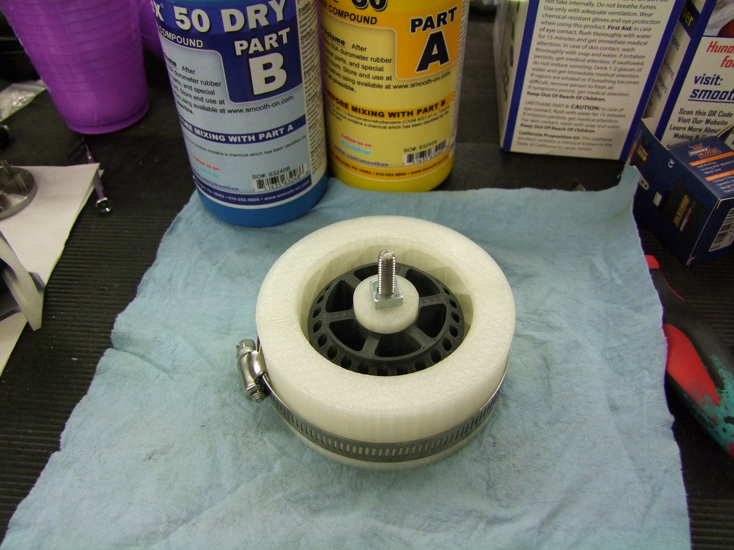
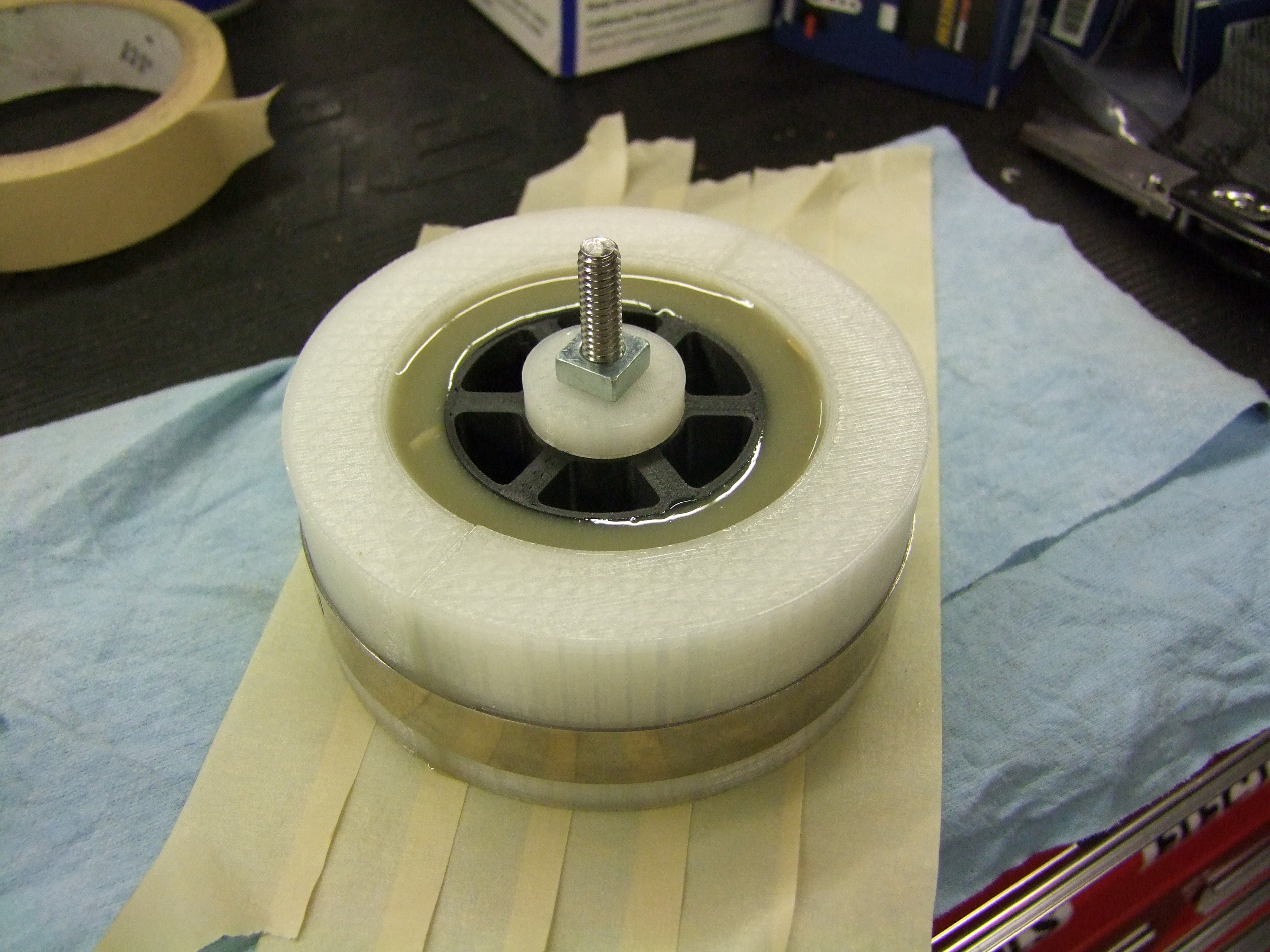
After the electronics are installed, I made the orange roundbelts and started closing everything up. The round belts are measured using the hypothetical pitch line in the belt circle drawing in the CAD model, then shortened about 10% to accommodate stretching.

The final act is to install the linkages. This is done using long M3 bolts cut down such that their unthreaded shoulder acted as the joint pin, but I could still put a locknut on the end.

Here is the finished bot from the flappy end.

And a photo from the ‘business end’.
So how does this thing work? Well, it doesn’t really. The serpentine roundbelt drive has too much friction for the Fingertech motors to overcome. While Stance Stance Revolution used two 22:1 Fingertech motors, they were direct driving small wheels. Each pulley adds some friction, since the belts need to be tight to transmit torque and the pulleys do not have rolling bearings, just nylon on shoulder screws. Roll Cake therefore could not move at all. I’ve built some pretty damn immobile bots, but this is literally the most immobile thing I’ve ever made!
You can hear the motors strain to move, slipping on the belt, and occasionally it scoots forward a fraction of an inch. That’s about it. In doing this, I actually burned out one of my 22:1 motors.
I began making arrangements to get some 33:1 motors from fellow competitors down in Atlanta, which should help the torque problem, and also began the search for small timing belts. MXL and 2mm timing belts come in 1/8″ wide / 3mm wide, so I could redesign the pulleys to that tooth profile. Then, the matter becomes if the Mark Two can hold the kind of tolerances needed for the tooth geometry to work out. I decided to leave that to Atlanta.
While the driving test was a bust, I did get a few flipper tests in with the drum going full speed. I’m glad to say that this part seems to work great. The servo engagement is clean and predictable. Here’s a test against a roughly 3.5 pound empty toolbox. Note that I don’t have anything springy or elastic that’s preferentially loading the linkage closed, so it depends on good firing servo timing to bring it back down.
That was actually the second test. The first test was against a heavier (4.5 pound) aluminum rail – coincidentally, the unmachined blank frame rail for Uberclocker 4. On this test, the deceleration of the drum was severe enough that the bot rotated forward against the linkage… causing the drum to strike the ground and hilarity to ensue.
Well, truth be told, that was the part of the bot I cared about. I packed all of the parts up for Roll Cake anticipating needing to do some re-engineering once I was on site. Just prior to leaving, I ordered two sizes of timing belts from SDP-SI based on the existing pitch length and what was closest to it – two 155 tooth 1/8″ wide MXL belts, and two 160 tooth ones. At least one of these will be close enough after I redesign the pulleys to be timing belt profiles with roughly the same pitch circle.
Überclocker 4.0
No fake-outs with wheels this time! This is the real deal now.
I’d been MEANING to retire Clocker version 3 (Überclocker Advance) since after Motorama 2015. Then came Dragon Con 2015…and then Franklin Institute 2015. After it won handily at FI, I decided to force myself to retire it, leaving the broken actuator unrepaired. Clocker 4.0, which has no witty Engrish name, was meant to be designed much earlier in the summer, post #season2.
Well that clearly didn’t happen… I actually started working on the design on and off in mid-July, but some contract work was keeping me entertained at the time – so designing didn’t start in earnest until August. That’s one side of being “funemployed” is that the work you do pick up is often stuff you like to do, meaning you adopt it as your own, meaning certain death if you have zero time management ability like me.
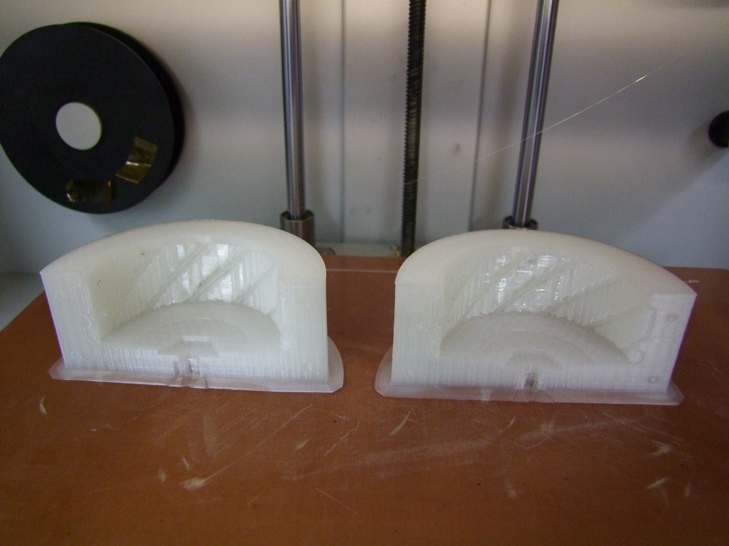
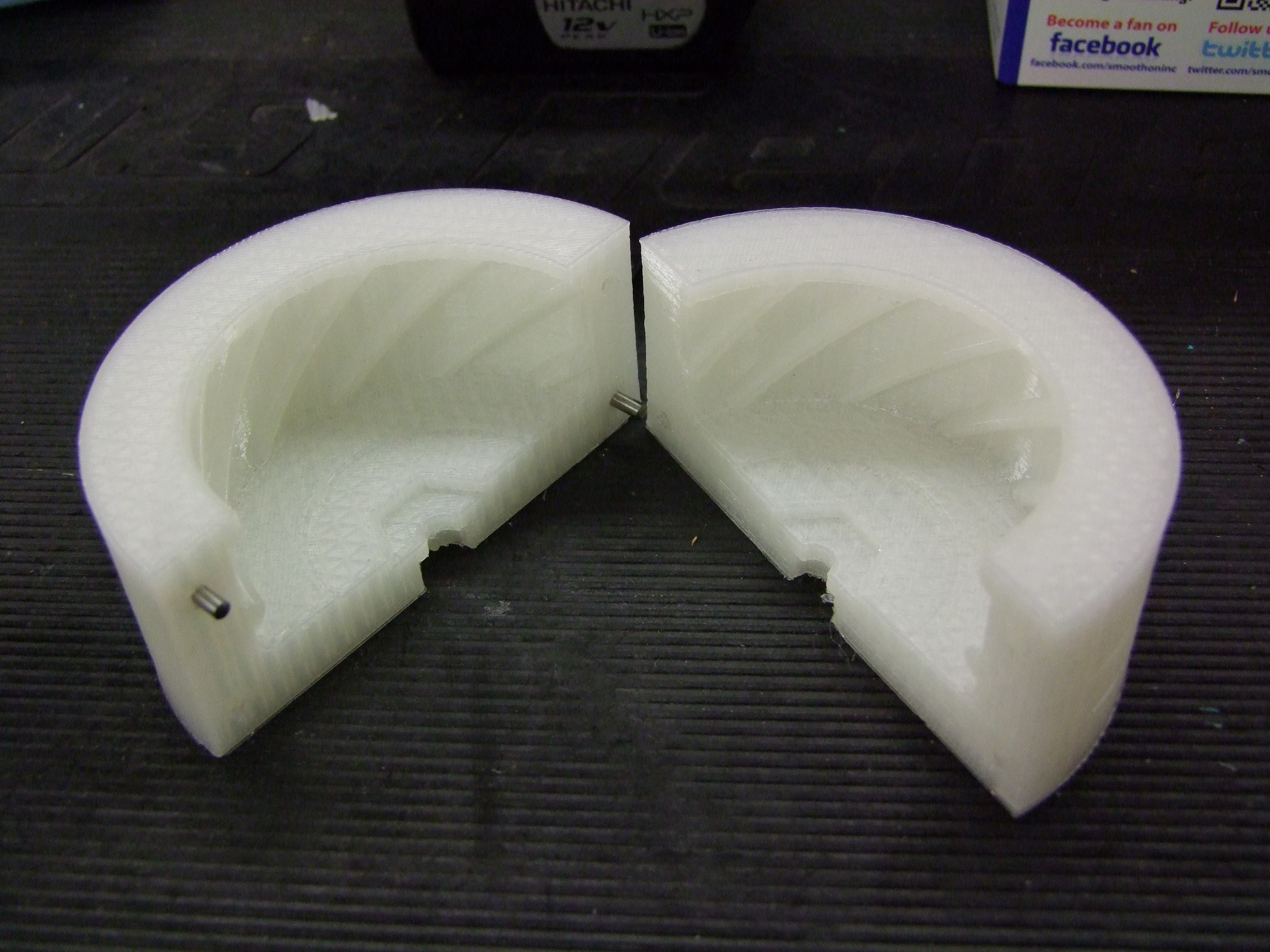
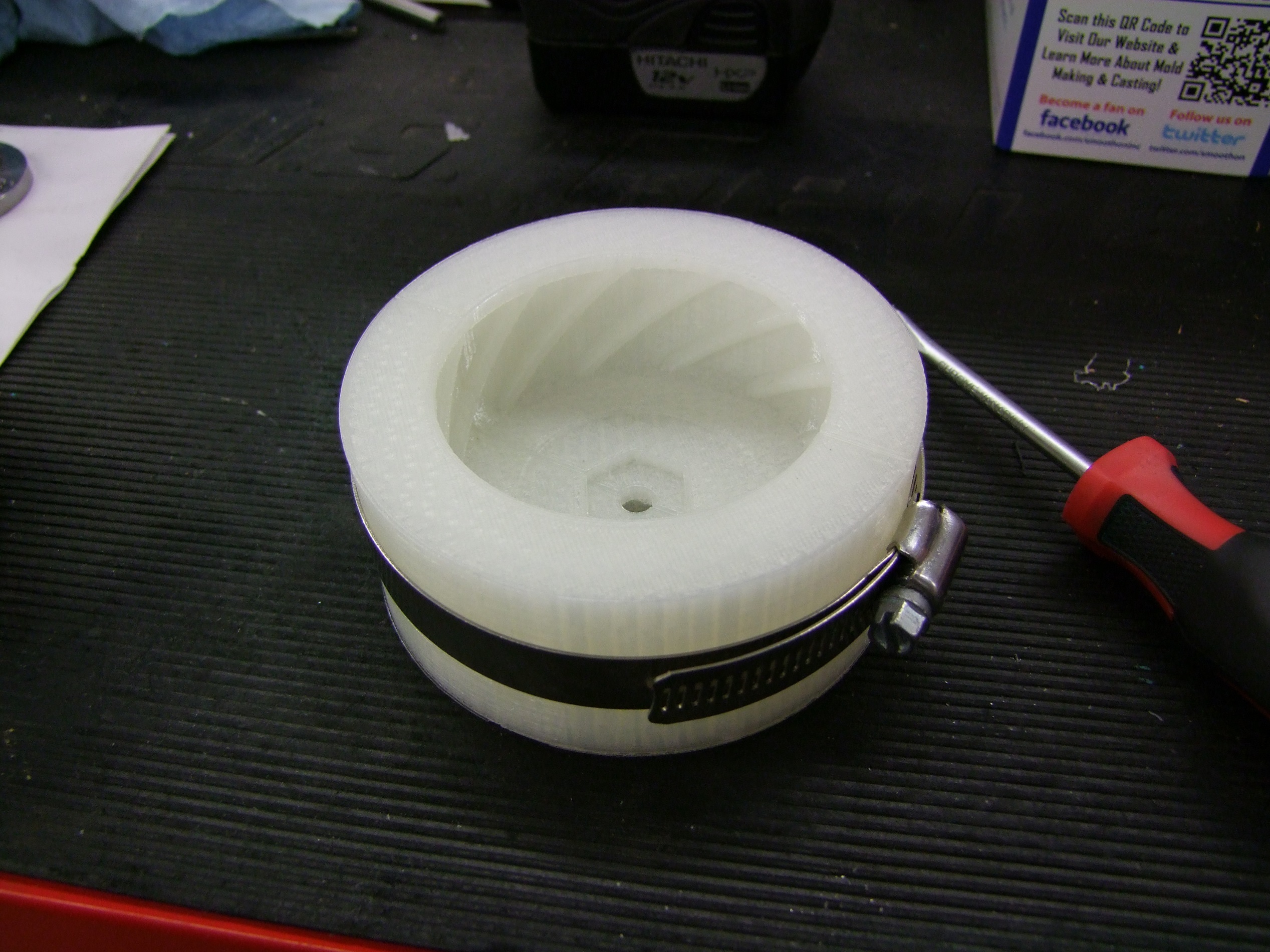
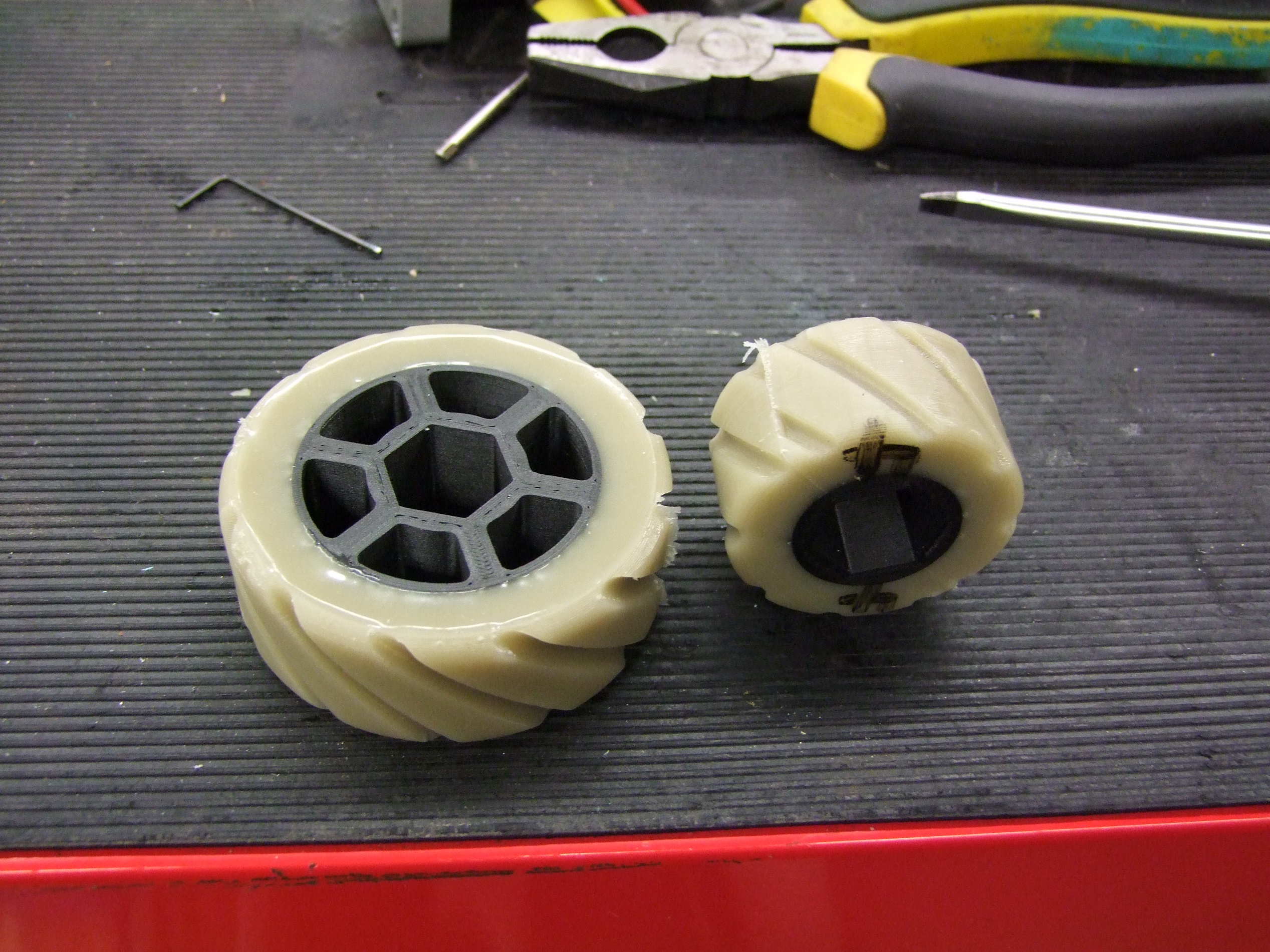
The first thing I designed up was actually the custom cast wheels that I talked about last time. I decided to use Clocker 4 as a smaller-scale experiment to try out the technique and different materials without wasting a bunch of money. The wheels were made with a 3/4 hex hub, which Clocker 3 uses and which I intend to carry over to the new bot. They were made in two sizes – 3 inch and 2 inch – to reflect the needs of the new bot.
So let’s go through the design of the bot now! Keep in mind through all of this that the principal design constraint was “Is this dimension about 50% of what it would be on Overhaul 2?” and is definitely a departure from my usual tactic of letting the part placement drive the robot. In fact, you could argue that both Roll Cake and Clocker 4 represent me trying to “design to look like something first” – Roll Cake being an old robot vision from years ago, and Clocker 4 being a scale model of Overhaul.

Just like with Overhaul 2, I began with a sanity check sketch to make sure the dimensions aren’t impossible. In this picture, the only things fixed are the wheel sizes and chassis height. Much like OH2’s design phase, I was going to let the length of the frame be malleable in order to fit components. But it should end up somewhere around 30″ in the ideal case.

I focused a little more on the pontoons first. The rectangles shown are a size of wubbie that is the closest to 50% scaled down from the type used in OH2. While their final shape and dimensions is not settled by this sketch, I just wanted to factor them in to get an idea of the size boundaries.

Bringing in more geometry into the mix now by playing with lifting fork lengths and the height of the arm towers.

Probably the terminal stage of The One Sketch has the 2.5″ square DeWut motor profiles imported, the length of the frame adjusted, and the first pass at the upper clamp arm also drawn. Most dimensions line up with OH2 within 10% or so, which is fine. Nothing truly scales directly in robotworld, and I figure so long as the visual is complete, nobody else but me will notice!

The beginnings of the 3D design went much the same way as with most of my bots, Overhaul included, with the generation of frame rails. You have to start somewhere, so I usually start with the back or left side, and everything sort of grows off that.

I imported the One Sketch and aligned it with the bot as a reference.

Moving on ahead a little bit, here is a more complete drive side. The front wheel is inset significantly into the plane of the front endcaps which hold the rubber shock mounts. I wanted to do this to maximize the wheelbase. Previous Clockers have had the “reactive outriggers” up front to maintain front traction when an opponent gets picked up. This version is relying solely on the rubber shock mounts deflecting, and it will be riding on the front edge of the pontoons thereafter. To maximize the chances of retaining traction in that scenario, I wanted to push the front wheels as far forward as I could.
This does open up a gap in the otherwise fully constrained tab of the frame rail, so here’s hoping that spamming the region with cap screws will make up for it.
Frame rail service for Clocker will also be a little harder harder than Overhaul. In this design, to pull the left frame rail, the pontoons and three of the six shock mounts have to be removed, and there is now more than 1 bit driver size needed. However, you could argue that OH2 also needed two bit sizes – 7/32 for the pontoon screws and 5/16 for the frame bolts.

Cloning stuff to the other side…

A very difficult step came afterwards. I now had to fit the DeWuts from Clocker 3 into this frame (I SOLEMNLY PROMISE DEWUTS WILL BE BACK IN STOCK SOON) . This presented a very serious problem, which is well summarized by NO.
You see, the average Featherweight, full-contact 30lber is generally much smaller than the Sportsman class bots, since they’re built denser with thicker materials to take KE weapon impacts. Clocker 3 is very large for a 30lb bot to begin with, at 20″ wide and 27″ long end to end, it’s almost the footprint of some of the denser 250lbers like Poison Arrow.
In order to make weight, as well as stay roughly true to Overhaul’s dimensions, Clocker 4 needs to be around 16″ wide. However, this utterly precludes the use of the DeWuts. I would need to make the bot at least 18″ wide to use them. That means proportionally more weight to cover the additional width of the bot, as well as a lot of inside space that’s kind of wasted lengthwise since more components would be able to fit next to the motors. This isn’t a bad thing by itself, but two DeWuts back to back kind of forces a different shape robot than what I was pursuing.

So I began working on the inevitable: going brushless with the drivetrain to save volume. I studied a few options which all revolved around a handful of AXi motors I picked up a few months ago (get yours today!). I borrowed a BaneBots P60 model since Jamison had already played with mounting P60s to the AXi motors. I also investigated stuffing the AXi motors into my spare P80s from Overhaul.
In the name of expediency – namely, that I had the spare P80 drive motors on hand, the AXi + P80 combination won. The 4:1 Overhaul P80s combined with the AXi motors at 7S (26v) ought to give a top speed of about 17mph, which is plenty.
The downside is extra weight. While the P80 and AXi combo weighs less than the DeWut, it weighs more than the P60 equivalent which would handle the motor power just fine. For Robot Battles where I won’t need extensive armor, I figured that letting the drive motors have 2 more pounds is fine.
However, I might actually swap these out before FI 2016 for modified P60s, since having the armor weight back would be nice.

Now importing more components – the space inside the bot is filling up fast!

I devised this quickly-3D-printable-from-Onyx mounting bracket for the AXi motor. A new pinion with a 6mm bore will be crafted out of spare 4:1 planet gears, which have 4mm bores I can hollow out.

So the AXi drive will solve the issue of width in the bot. I’m now toying with placement of the internal components. To start with, I’ll be using two of the spare DLUX 160A controllers I took out of Overhaul before the Season 2 tournament began, with a possible upgrade to Brushless Rage later using a 6-FET board (think Brushless HalfRage)

I settled for the two DLUX controllers up front mounted to a (not yet modeled) non-structural interior bulkhead, and the RageBridge in the rear corner to handle lift and clamp, also with a yet-unmodeled bracket.

Let’s begin on the fork tines now. I traced out the basic shape of Overhaul’s fork, but unlike Overhaul which uses a dead (fixed) lift shaft, I’m keeping the live life shaft of Clocker 3 since it’s fairly easy to attach to. The force transmission will be using clamp shaft collars made into hubs. There won’t be a central tube structure in the fork – both will just be held together with standoffs. The forks should, like in Overhaul, never be taking direct impacts unless I messed up horribly.

After I imported the quick fork model, which is still missing specific details like standoff mounting, I also began playing with the clamp actuator. I imported a few older Clocker actuators to check size and placement.
For this edition, I really wanted to move back to a full 550 motor actuator. This should actually give the bot a clamping force of several hundred pounds, which I wanted to have since most Featherweight class bots have negligible top armor.
The issue wasn’t so much weight (it would weigh around 1 cheap drill motor) as space. It had to fit in between the side plates of the clamp arm, first of all, and then anchor itself in a useful location that won’t impede the fork travel much. Overhaul has some issues with this which I would like to remedy for #season3 – so in a way, this is once again using the small bot to pilot something for the big one.

More details have been modeled into the fork plates now. The cross holes will have standoffs like good ol’ Clocker, not just to hold the fork sides together, but keep them level between arms. Overhaul has no such crossing feature near the tip of the arms, only the base. This was the cause of the forks becoming cockeyed during the Beta match when it got a good boop in on one of them, and I’d definitely like to solve this problem.

I decided to pursue the full 550 motor actuator at all costs, so I made one similar in construction to Clocker 3’s final actuator. The motor and gearbox? Just a 12 O’Clocker spare motor! The gears will be purchased from Vex, then modified – one to a 12mm bore, the other bored out to shove an Acme nut into.
Not shown in the above image is an “anti-buckle” MarkTwo printed piece that bridges the two thin plates and cradles the leadscrew for more of its travel. The actuator sides are in tension when clamping, but will be subject to sudden compression shock if the bot lands upside-down or I try reversing out of a grab, so I didn’t want to count on JUST 1/8″ aluminum plates.

Here it is loaded in place and showing placement. The upper anchor point was open to negotiation because the clamp arm sides hadn’t been designed yet. The lower anchor point for the leadscrew will just be a pin that is shoved through the first hole in the fork side plates, closest to the pivot point. The neat thing is this is somewhat adjustable for leverage ratios if I choose to use another hole instead.

I generated the fork side plates based on the dimensions of the One Sketch. It, too, will be held together by a bunch of standoffs – no welding here. This drawing shows some possible standoff positions. I was going to alternate inside and outside circles as I moved from left to right, like so:

The standoffs used are just some big McMaster-Carr 5/8″ hex aluminum standoffs, which for some reason are almost half the price of the neighboring sizes.
Actuator placement was a compromise between “How far does the motor stick out the top?” vs. “How far does the motor stick into the grabbing region?” since I could make the leadscrew as long or short as I pleased.

About this time, I threw Clocker 3 into the CAD model. The size different is almost comical, and at this point I wondered if Clocker 4 could pick up anything at all without falling on its face. Definitely will have trouble with the average 30SC sized bot, but again, 30lb Featherweights are smaller in general.

Anyways, moving on.
One of the next mods I want to make to Overhaul is what I call the “Anti-Cobalt System” – in other words, putting something between the frame rails so this doesn’t happen again. For Overhaul, I’ve been mentally designing it as a top and bottom plate fastened together in the middle, to close off the box and transfer sideway forces more rearward in the bot.
Since Clocker will now be competing in a high-energy class, I decided to implement the ACS for the most part on the bottom of the bot. This also acts to keep the drive chains above the plate, so they’ll be less vulnerable. I could still see this having a failure mode where in a very energetic sideways hit, the frame rails will deform in a parallelogram between the ACS plate on the bottom and the angled endcap on the top.

I’m now in the stage of generating top and bottom plates as well as random spacers. MarkForged spacers for everybody!

The single tooth will be made from some left over 1/2″ AR500 steel – good enough for the task.

I began the process of making the armor pontoons using the same method as on Overhaul. I made a master 2D sketch that represents the front face, and then a series of 3D Sketches thereafter, then defined surfaces using the sketch lines as their bounds.

The geometry for Clocker 4 is a lot simpler. There are no vertical forward-facing or side-facing wubbies, just the six widely spaced ones on the angled face. In a future revision I may consider adding forward-facing ones like Overhaul, if this decision comes back to bite me.
One major difference with these? They ride a lot closer to the ground than Overhaul’s. In fact, I will most definitely have to finish-grind the bottom edge to get enough clearance to not get hung up on them.
This is a good thing, because it resolves the other weakness of Overhaul that was clear during the beta match – the pontoons were simply up too high to be helpful, being designed to take a whomping instead of be good foot-in-the-door implements.

An overhead view of the bot basically done – you can see the standoffs between each pair of fork plates, the tie bar between the forks, and the tube which acts as the anchor for the leadscrew.

I added tabs and slots the same way as on Overhaul to prepare the pontoons for cutting and welding.

Here’s the finished bot minus cat ears!
The ears don’t seem to be necessary on Clocker 4, but it just doesn’t look right, man. I will probably design a pair up to be printed in RMCC which will bolt to the topmost hole in the clamp arm.
I left design of the internal brackets as an exercise to be done in Atlanta, since by this point I was running up on the last week available for fabrication. Hot off the CAD presses and into real life we go!

Man, it’s been a LONG TIME since I’ve done a one-shot epic waterjetting session to pop out a robot. Pictured above is the “Clocker kit”… or some 10 gauge mild steel, 1/4″ 1/2″ and 3/4″ aluminum, and some 1/16” FR-4 laminate.
Sadly, in my cruftiness, waterjetting is no longer free – this is probably around $400 of machine time.

To prevent the FR-4 from delaminating, I brought back one of my tricks of cutting the outer profile only, and using another material as a template. So here’s how this part went – I routed the parts manually to ensure it does all the interior holes first, then the outer profile.
I laid a piece of plywood in the machine first and had it cut only the holes. Then I clamped the FR-4 on top of the plywood and continued the toolpath to cut only the profile. The 1/2″ plywood pieces then become drilling templates for conventional drilling of the holes later, which otherwise might (WILL) delaminate since they’re piercing close to the edges.

While the design was slow-cooking to completion, I continued casting wheels, making 4 of each total. I’ve basically gotten this process down, so the next step is to try out different materials.

Here, I’m readying the frame rails for countersinking and counterboring. It’s built in the same style as Overhaul, and also many 30lbers and 12lbers. The frame rails will need machining to key into each other slightly too.

One of the last operations I was able to pull off before having to depart for Atlanta was the coring of the large lift gear. This was done using MITERlathe and like 5 different tools. MITERS didn’t have a spoon-type boring bar to make a plunging face cut easy, so I had to make do using a few different types of insert cutters, switching left-hand and right-hand tools to clean out the blind pocket.

Sadly, Monday the 28th of August was upon me. I actually spent more time in the week preceding finishing Roll Cake, since I cared a lot more about perfecting that mechanism, so Clocker 4 fell by the wayside. Clocker traveled to Atlanta in kit form, shown above. I needed to do some (lol) work on it in Atlanta, such as milling the frame slots, before it could be assembled.
And that’s the bot half of the story. Next, what about the convention!? I came this far for something, I think. Whatever is causing all that noise next to the robot events, dammit!
Robot Battles & Dragon Con 2016
So before we get to the convention proper, let me interject with a proud announcement that…

…I finally got pulled over for speeding.
You didn’t think it was physically possible, right?
I’d like to thank my parents, uhh… Boston area highways…. and, of course and Smooth Automotive for the Accidental Engine Rebuild of 2015 which has restored Mikuvan’s former power so much that I legitimately now can speed. I mean, it takes a little while to get there, and no hills please, but otherwise, I can cruise at 75mph all day – just enough to get in trouble in Virginia when the speed limit drops to 60mph for an upcoming work zone and I ABSOLUTELY, POSITIVELY MUST PASS THIS ONE LAST MOTHERFUCKER ON THE RIGHT HERE and… Dammit.
He got me fair and square. In fact, he didn’t even mention how I Boston’d someone immediately before the orange construction barrel forest began. So thank you in that way, Virginia State Trooper. I’m not even going to look at this ticket until I’m back in town now, because Virginia sucks.
Alright, enough of that. As I mentioned at the beginning, there were no van shenanigans to be had. I got into town around 4:30PM Wednesday, and immediately began plotting robot finishing tactics. The first order of business was getting Roll Cake its timing belt setup, which I designed quickly once I settled in and put on print. What?

Yes, I dragged the Mark Two provided by my lovely sponsor MarkForged along. Hey guys, how’s about some hot and humid weather testing?!
The SDP-SI timing belt order arrived on Thursday afternoon, so I could test the fit immediately. More importantly, though, on Thursday…

I busted into Dale‘s shop like the good ol’ days and basically took over his entire workbench. On deck were finishing some milling and turning parts for Clocker 4. I machined the axles, finished off the wheel hubs, and made the motor pinions, among other unfinished business.

The big rear chamfer for the frame rails was also cut by tilting the head of his CNC mill 30 degrees.
Friday bot work was mostly done at the GT Invention Studio. I primarily worked on Roll Cake, doing the final installation and tuning of the timing belt drive:

The pulleys were sized by how close they were to the pitch line defined in my belt loop sketch. The difference was then made up by changing the motor pulley tooth count until the tension was reasonable (just going from 21 tooth to 18 tooth in one try was enough).
This worked….. a little. Roll Cake’s movement was still extremely strained. There was no binding of the drivetrain anywhere I could see, just that there’s too many moving things for the 22:1 Fingertech motors. It moved slowly and quite arduously, and still could not turn.
Well, there wasn’t much else I could do to alleviate this problem except swap to the 33:1 gearmotors which I was able to pick up day-of MicroBattles from Mike Jeffries. Before the event started, I went ahead and did the motor transplant.

Operating sheets and all! This was so I didn’t get any abrasive/metallic grunge into the bot while cutting down the motor shafts.
The end result? I got Roll Cake to move somewhat reliably on the floor, so I went ahead and decided to put it in its first match anyway…. against Kurtis’ Black Adder.
Dammit, Kurtis.
Unfortunately, in the arena, it moved all of 18 inches or so before farting out again. It at least managed to flip Black Adder over with a chance collision. At this point, I stopped caring, since watching the mechanism test fire was more important to me than the rest of the bot, so I just kept flapping until the end.

Poor Roll Cake. It had such a bright future.

Okay, not really.
So the flipper mechanism kept working up until the end, even though I technically never got a direct shot at Black Adder.
That’s okay – I’m already out to rebuild this thing correctly such that it’s mobile. Roll Cake 2 will just have two brushless gimbal motors for drive, as hub motors, with the same Afro30 SimonK-enabled controllers driving them. It will have 2 larger wheels up front like a classic drumbot, not this 6WD business. Since Stance Stance Revolution could basically drive upside-down on its two discs, I’m much more confident in this setup working.
So that’s it for Roll Cake. Now back to your regularly scheduled Überclocker:

In the same work session as finishing out Roll Cake, I assembled all of the modules within Überclocker – the actuator, both drive motors, wheels, and the DeWut for the liftgear.

On Sunday afternoon, I returned to Dale’s shop to make a mess one more time. This time, to carve out the giant pocket that is in the back frame rail, formerly solid 6061 aluminum. Final weight estimates showed that I did need around 1.2 pounds out of the frame rail, so I calculated the pocket size needed, gave it some more oversize for weight tolerances, and went to town.

The next operation in Dale’s shop was putting some pilot holes into the end-tapped frame rails. I figured I could run with 1 bolt in each frame rail for now, and then drill them later once I had access again to a large drill press back at Artisan’s Asylum or MIT. This let me put most of the frame together on Sunday evening.

After I went back home, I did what I could using the remains of my high school workbench, which contained a small 10″ drill press, hand drill, and jigsaw, plus the hand tools and cordless tools I brought down, and a few kibbles of tooling that I didn’t take up to Boston with me originally.
The above was…. basically all that I could do. Mount the shaft collar to the big lift gear using a counterbore I brought. I didn’t even have any clamps left, and by the time I got back home, all of the hardware stores and home improvement stores were closed for Sunday night. I tried drilling and tapping a few of the frame screws by hand, which was an arduous procedure. I basically called it quits around 6AM Monday after trying to work on putting it together all night, and not getting much further than 10 or so drilled holes.
Basically the most important part of having tools is having consistent tools. Maybe these tools were enough for me during high school, but I also built bots in completely different ways to accommodate them (e.g. making things from UHMW plastic). Designing for tools that are not consistently available, or totally unavailable, will just end in disappointment. I realized no matter what, I could only hack Clocker so far in the remnants of my parents’ garage if it depended on a full service shop to be put together.

So here is the assembled husk of Clocker 4 next Overhaul at Robot Battles on Monday, showing what could have been if I didn’t kick my own ass… or as Will Bales puts it, Will Balesing.
By the way, shoutouts to Matt and Dan of Chaos Corps for taking the pieces of the pontoons from me on Friday and returning them completely welded on Saturday. Not just welded, but all ground and wire brushed. I owe you guys a small water balloon filled with argon!
But wait! The story doesn’t end there!
I also brought 12 O’Clocker along, figuring that I’d be able to run something in the Monday event at least. 12 O’Clocker was working fine after Momocon, so I basically packed it right back up with some spare motors. The clamp motor on it was a little baked, so I reached out to the group for spare Kitbots/1000rpm-style motors.
It actually got a few matches in and entertained the audience immensely.
In the rumble, the lift sprocket got bent hard enough to pop the lift chain off. Otherwise, 12 O’Clocker takes no damage once again! Gosh, maybe I should just scale this thing UP instead of Overhaul DOWN, right?
So no prizes this year, and not a very good Dragon Con for robots. I’m going to continue finishing Clocker 4 in the interest of Franklin Institute Robot Conflict 2016, where I hopefully will get to play with some of the big energy bots. I never had a strategy for Overhaul against vertical weapons like drums and discs (e.g. Hypershock, Witch Doctor) – besides Don’t Get Owned, I mean. I hope the Featherweight class, which is full of vertical spinners, will let me fine tune how to approach bots like that better for #season3.
By the way, there was a trip to the new Atlanta McMaster-Carr warehouse to pick up last-minute hardware. This place is

…kinda big.

Okay, REALLY REALLY BIG. Douglasville and the surrounding west Atlanta area is kind of a new target for development, and besides industrial plazas and The McMastergon, there were plenty of housing developments. What could be better than stumbling out of bed and over to Will-Call to pick up your last night’s blurrily-assembled orders? Or hell, just wheel the robot over and work on it in the Will Call parking lot. It’s like working on your shitty car in an Advance Auto Parts parking lot! Who the hell’s ever done that… not me! Nope, never.
So wait… wasn’t there an ENTIRE CONVENTION going on besides just me working on robots? Absolutely… so let’s see how that went.

As usual, I’m too lazy to put together a worthwhile costume, so I went lazily all days as “me”. Just the Overhaul team shirt, and also wearing the Axent Wear headphones around.
I got stopped way more times than I expected.
Shown above is the crew of Jamison, Cynthia, Hannalin, and Lucy, formerly all of JACD last season. This year’s group is Overwatch. Overwatch is a video game. I haven’t played a video game with any degree of seriousness since Descent II Vertigo. I assume this is all legit. Wait until you see the construction Cynthia put into the giant bow…

There was a massive Overwatch photo gathering which took us an hour or more to get out of. Pictured above in the group are Pizoobie and Bonnie.

I generally haunt costumes which have had a lot of work put into them, especially very large and unwieldy ones. I swear at some point I will make an overly complex and elaborate costume. You could argue that Overhaul is in fact such a prop.

This was cool, too. These guys were cruisingly slowly around the convention. P I P E S

Okay, I don’t even know what’s going on any more. Overwatch players, I assume this is something you’d understand.

Alright, I usually don’t give a spare minute for Kantai Collection because it’s utterly destroyed my favorite genre. But I will make exceptions for well done ones. Behold, the U.S.S. Iowa. I watched her being “assembled” on the spot, and before that, I followed the ant trail of battleship parts being carried high overhead down the packed street by her pit crew. Her drydock workers?

Good ol’ Kancolle, ruining “girls & machinery” since 2013.
If you know who this U.S.S Iowa is, let me know and I will gladly add links and creedits.
Now here’s how to properly do it. Besides Overwatch, Cynthia, Lucy and Hanna also teamed up for something else. Shamelessly stolen from the BattleBots Instagram, it’s….
I’m telling you all, #season3 will be one big weeb convention. Everything is falling into place, exactly according to keikaku. Cynthia is the designer of Haru-Chan, so it was only natural that she also sketched up plans for Sawblaze and Road Rash.
Now for the event recap!

MicroBattles this year was bigger than ever. With the insect classes (1s and 3s) being the easiest and cheapest to start in, the newbie and first timer proportion this year was immense. We ended up getting over 40 robots!
Sadly I actually missed a lot of the action getting Roll Cake prepared, but here are some of my favorites.

Here we have the wild Killer Colsonbot, which is believed to have evolved from escaped Domestic Colsonbots.
That’s Pvt. Slicer, or what happens when Mike gets ahold of the Colsonbot CAD. The cage is made of layers of waterjet-cut 4130 steel carefully welded together. It had friction drive reliability issues, but it somehow won 2 matches as round pushybot. When the cage met a vertical spinner, it died.

Representing the “meh” department of Dale’s Homemade Robots, this is Noodles, a 4wd pushybot. Besides all brushless drive, steering gyro, and a crafty urethane-sheet-mounted steel plow, it has pool noodle wheels which caused a bit of controversy because in the final a piece of them came off and jammed Black Adder’s drum.
Now, unintentional entanglement is allowed in the rules for the precise reason of a part inadvertantly coming off and getting stuck in something (as opposed to intentionally throwing things into a weapon to jam it), but there was still a fair bit of “Who do you think won this match?” talk. I actually think repeatedly hitting the ceiling against Black Adder and coming back each time is a mark against the effectiveness of Black Adder’s weapon in this match.

It’s big bot time! After being forced to run 12 O’Clocker only, I had more time to go around and appreciate the 12s and 30s. The newbie count was great at this event also – I think probably 25% first or second events.

Pictured above, The Magical Lipo-Fire or…. something or other. The build looked great! Sadly only one match however, and fortunately did not live up to its name.

First time 30lb entry “STICK A FORK IN IT!” which was having some DeWut clutch issues this event. Hey, people, read the manual! Tighten down your DeWut clutches before using!

Team JACD Season 1 principal cheerleader Andrew brings Pusheen-Bot, a pushy-bot. It’s laser-cut out of wood, so naturally it faced a chainsaw first match. This thing actually has two 50mm outrunners in it. It’s basically BurnoutChibi in a 30lb bot, so-illustrated by Andrew riding the bot around the room before (and during…) the event.

Another new 30lber with some heavy inspiration from Clocker and megaRon (under whichever moniker Jamison decides to run it at Robot Battles…)
There were obviously a lot of bots that I skipped, and you kind of get the idea. With the return of BattleBots to a mass audience, so the hobby grows! Robot Battles, fortunately, is one of the lowest barriers-to-entry competitions there is.

12 O’Clocker all set up and with spare clamp motor installed, ready for its first match. I had immense fun in its match with Dingleframus – it was the hardest physical driving match I’ve had in a little while, and in the end, a missed charge basically caused it to hover off the stage.

Here’s “Metric Brushless Hipster 12 O’Clocker” LiftLord, a Xo creation but shown with optional interchangeable Aaron module.

12 O’Clocker ready for its first match against Abrasive Personality, a design I really want to see more of – it has a belt sander running the length of the bot, with a backstop and all. I think this kind of design needs exploring. Putting more horsepower behind it and using a super gritty belt might actually result in some serious unconventional damage.
So what the hell are those blue things on the stage that have been appearing in every video so far?
They’re my secret weapon: 3D printed model set screws. I printed about a dozen, then another dozen or so followed me to Atlanta courtesy of RocketProps. Some local folks contributed a few more…. and suddenly, a stage full of giant set screws. Robot Battles: serious business since 1967 or whatever.

Not sure what I was doing here – probably double checking the chain drive after the rumble where it was derailed due to the main sprocket being physically bent. 12 o’clocker went 1/1 plus hanging around during the rumble, which was hugely entertaining.

Well look who’s on display! I’m told that Witch Doctor & Hypershock were also going to be present. Lies! I didn’t see any of y’all this whole weekend, so Overhaul had to have all the fans to itself. Such a sad day.
That’s a wrap for Dragon Con 2016. Once again, I’m staying a few days extra in Atlanta, and will diffuse back up north some time this week. On deck for robot work is finishing Clocker and a quick revamp of Roll Cake before FI in about 1 month. Otherwise, I’ll be hopefully creating more problems for myself with van work soon, since I want to re-winterize a few spots before things get cold (e.g. in 2 months or so). Some of my earliest rust repair is starting to come apart finally, and I have better weaponry against it now. Further down the line is word about # s e a s o n 3 and starting Overhaul….overhaul…. work in earnest. This will ideally occur over the coming winter.


