It’s time.
Time for what, Charles?!
It’s…

ROBOT FIGHTING TIME!
I bet nobody saw that one coming! It’s always robot fighting time here at Big Chuck’s Robot Warehouse & Auto Body Center! I’m your host, Big Chuck. And today, we’re going to talk about OBAMA’S ANTI-WEDGE AGENDA flywheel flippers.
Actually, let’s talk about all stored mechanical energy flipper weapons. I’m talking about flywheels and springs, but not including pneumatics. Those former two approaches have been rare penguins in the world of robot fighting, and I think there have been only a half-dozen or so successful ones, meaning it worked consistently or at all. They both need methods to carefully input mechanical work, decouple the source, and then carefully couple the storage medium (be it flywheel or spring) to the output.
One of my metrics for how difficult a design is to pull off is how many approaches there are to the problem. I always love to pick on the “small vertical drumlet” design as an example. If you take a look at the registration field of a big open event like Motorama… or hell, even BattleBots Season 2, you see a lot of the same design topologies show up repeatedly. In the open-arena environment, those designs are the apex predators, and over time, the design space gravitates towards them. Almost all small vertical drumbots look alike and have the same idea about weapon design and drive, because it’s what’s proven to work, and if you want to win, you want to build what works.
On the other hand, just about every flywheel flipper which has existed has used a different approach to “access” the energy stored in the flywheel. You have the direct flywheel-coupled low speed punter and the automatic-tripping dog clutch of Dale, the “Jam a Colson in it” of Magneato and Zach’s previous bot Jack Reacher, and the face-cam spinning ring of Warrior (which probably has the all-time flywheel flipper high score).

The inside of Warrior (Clan…Dragon… SKF) showing the cam ring and notched linkage which rides in it, released by a servo.
Original photograph by BoomBots, rediscovered later by Kevin Hjelden
That, in my opinion, is how you know a design is still a challenge. Not to dismiss the effort that goes into building a small vertical drumlet, since reliability in a design is always difficult to attain. The way I see it is that the less a design is “settled” on a single approach means the less people have attempted it. When it comes to spring and flywheel flippers, the engagement of the flywheel is always the sticking point. It inevitable requires tricky machining or unwieldy linkages and couplings, or clutches. Get any of these wrong and you just make a kinetic energy grenade in the arena, which is fun to watch for everybody except you.
Now, I have a fair bit of history with trying to design flywheel flippers and spring flippers. It’s in fact one of the designs I’ve tried to work on the most. For example, we now take a trip back to 2006. I had to rummage through not one, but two old hard drives to find this photo directory!

This was the first time I put together a “two ended” bot design. That means it has an active KE weapon that’s also used to actuate a flipper in the back. I had an interest in a design like this for a long time due to the existence of Warrior, but wanted to see it in a vertical spinner; at the time, Nuclear Kitten was still quite successful (I was, you see, the prototypical Small Vertical Drumlet kid, and this gives me infinite hipster cred, right?). After Dale build the 2nd OmegaForce, I thought that the triangular shape was well-suited to a design where the flipping linkage was a scissor type design, which just hinged on the bot, riding the ground, until commanded to open up.
It was always this opening up which was the hard part, and in fact this is as far as that design ever got. I can find no additional photos or Inventor files relevant to it.

Fast forward about 5 and a half years, and here we have the bot for which the original wubba-wubba drive post was made. This is the first time this design is being made public, because it never got far enough for me to want to write a design post. I designed a few variations of the “KE kicker” weapon, which was an internal flywheel (the large aluminum shell stayed still and the “Hard drive head” looking thing spun around it) geared around 40:1 to the kicker.
The actuation mechanism was a one-sided Differential Analyzer style torque amplifier (reasonable video here). God that’s a lot of link text in that sentence. Essentially, the post-geared flywheel spun a winding drum, around which a steel cable was wound loosely a few turns. The steel cable connected to the scissor linkage on one side and a small winch motor on the other. When the winch motor pulls on the cable, it tightens around the drum and transmits the force instantaneously to the linkage. As long as the winch motor wanted to spin faster than the drum (i.e. apply a force on the cable), the linkage would move. If the winch motor stopped, the force is released to the degree that the flipper linkage tries to pull against it back downwards. If the winch motor is powered the opposite direction, the linkage closes again since the drum cannot grip the now loosened steel cable.
It was something I read about in a textbook, then tried winding a string around a spinning motor shaft and pulling weights with it across a workbench. I was confident this idea would work. The ‘winch’ was just a fast DC motor running a sector gear that had hard stops, such that in one rotation of the drum, the motor is forced to stop and reverse, and that linear distance covered by the drum rotation was enough to fold the linkage out.
The design above did not progress further because it was too heavy. My desire to keep the mechanism coaxial made it too heavy. Furthemore, I recognized that the motion only worked in one direction. There was no powering closed, only gravity and any springs I put in the flipper mechanism to help it back down.
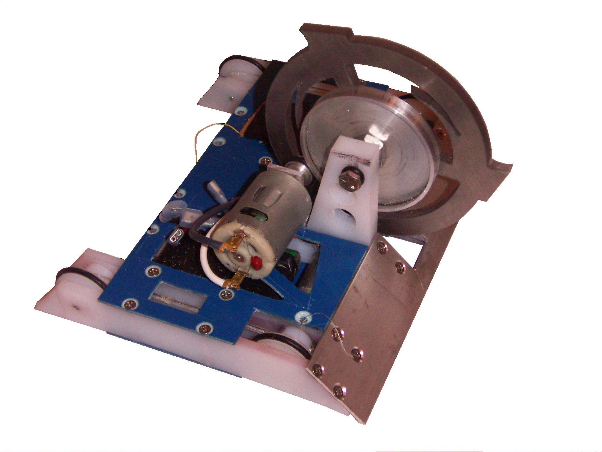
That didn’t stop me from making an updated less-heavy version of the kicker, which involved an external flywheel:

Now, this flywheel was super interesting, as I had forgotten I ever designed it. What you see is a P80 gearbox with a brushless motor built onto it.

Yup, you can tell this was thought up in my Era of Designing Silly Hub Motors. P80-flywheel-motor!
In the end, this design also never progressed beyond the point shown. And I honestly am not sure why – I may have lost interest and moved onto rebuilding Überclocker, or I still thought it was too messy to work well.
By the way, another artifact from late 2006 in my “D:\old\Backup of C\old\pics\old\….” directory was this:

That’s a Test Bot version 5 concept with a spring flipper. Looking back at this mechanism from where I stand now, it’s clear to me that I at least learned 1 or 2 things at MIT, which I think was the idea of going in the first place. The mechanism, while sound in theory, has a lot of nuanced problems that would have made it not work.
The idea of the mechanism was that there was a block with a ratchet/hook (think roller coaster climb ratchet) which could be moved along the bot via leadscrew. The ratchet preferantially springs towards the center of the bot and can grab a movable block which compresses the spring as they travel along the leadscrew. At the end of travel (back of the bot), a small ramp structure forces the ratchet away – this structure is not modeled here) and pop goes the spring. Then it has to travel all the way back to the start and hook the ratchet over the block again to reload. Works in principle, and I can see it working IRL with some critical geometry changes.
This, too, was as far as that design got – those who knew me in that era would know that I went to a standard 4-bar lifter for Test Bot in 2007.
So, as you can see, I’ve had a lot of false starts when it comes to these things. For the longest time, in fact I’d say since I produced these first designs in the mid-2000s, I’d never attempted to build them, writing it off to “Well, Dale and Whyachi have already done it more elegantly than I can, so why bother”, and distracted myself with grabby-bots and vehicles of questionable utility to society.
Well that’s kind of a shitty attitude, isn’t it? And one that I keep trying to beat out of others, such as my former students, whenever I had the chance. So why the fuck don’t I just take my own advice?!
People who read the MarkForged blog might have already seen a preview of this design. I wrote that article as a part of their marketing push for the new Onyx material (which is currently the only 3D printing material I care about), when this design was in an earlier stage. It was also heavily summarized for a general technical audience. Now, it’s time to dive into the full gory details of development!
Wubba-Wubba Drive’s Revenge
I first began reading about compound planetary systems (Hereafter: wubba-wubba drives) for a MIT Media Lab project during my freshman year in 2007, when we were trying to package a high-ratio steering servo inside the wheel of the CityCar project. I mentally filed the WWD away as a useful mechanism, but the filing cabinet was in a mental block scheduled for demolition due to blight suffered from Charles’ Angsty Emo Middle School Years, and as such the record was lost.
So I forgot about it until the BO-Px motors in 2.007 showed up, and it renewed my interest in exploring it. That’s how the “Wubba-wubba-bot”, which was never named, came to be. It was a compact way to get the reduction I needed without multiple stages of planetary gears.
After the BattleBots season was over, I was looking for another “family” of robots to build, so to speak. The past couple of years have seen me rebuild and revise Überclocker, my clampy-grabby bot bloodline. With Clocker finally retired (FOR REALSIES) after its tournament win last Franklin Institute, and with the summer robot season in effect, I was thinking about what other less-loved design to pursue for the next little while. A lot of conversation with Landon (of The Dentist) about flywheel flippers… because, I love you guys, promise, but let’s make the Dentist even more out-there for #season3…. made me remember the Wubba-Wubba Bot and how I left that design hanging in space.
What if I started with a small concept and grew it eventually larger and larger? One of my problems was starting with a 30lber, I think. It made for too much of a material and effort investment into something which would probably not have worked. And with my recent habit of 3D printing stupid beetleweights, it was abundantly clear to me that a 3lb concept would be the way to start. After all, I had recently scrapped both SSR and Colsonbot ( RIP ), so had spare running gear for a small robot.
I still lacked a way to actuate the linkage that was satisfactory, however. One of my reservations about the cable-driven system was that it only powered on the opening swing, and could not apply force the other way. Furthermore, if the flipper were forced open externally or could not close (something caught under it, mechanism damaged and jammed, etc.) there is a risk of the cable bunching up and becoming tangled. A possible failure mode is the bot getting stuck with the scissor link open upside-down (or facing straight up) without the ability to close the linkage again.
All hypotheticals, but a design like Warrior poweres both on the upswing and downswing. When I was designing the Wubba-wubba Bot, I briefly entertained an alternative engagement mechanism which was brought back up while talking about designs with Landon.
The best way to describe this method is probably to watch this video of my ‘toy gearbox’ that I made for the design:
Here’s the first rendition of that toy gearbox, showing the split ring gears and compound planets – planet gears of slightly differing tooth count, but conjoined.

The way this new triggering mechanism is intended to work is that stopping one of the ring gears forces the other ring gear to spin at a speed determined by the compound planetary gear ratio. Stop the other, and the former rotates in the opposite direction at the same ratio. Basically, you pick a “ground” (zero velocity) and the other output is forced to spin with positive or negative polarity.
Say for example one ring gear is connected via a cam linkage to the flipper (the ‘cam gear’), and the other is ordinarily free to spin, but can be stopped a large brake or dog clutch (clutch gear). The stopped clutch gear becomes the ground, and the cam gear is forced to rotate the linkage. Let go, and the linkage stops the cam gear from rotating continuously, so the clutch gear goes back to freely spinning.
This method was one that I discovered by accident in 2012 spinning the WWD model, but I was intent on exploring the Torque Amplifier cable-driven method. When the original Wubba-Wubba Bot design was shelved, so was this idea.
The advantages of this method of engagement include a large cylindrical engagement surface which can be arbirarily large (e.g. to act as a brake band rotor, or give more surface area to a big magnetic clutch, etc.) and an all-mechanical power transmission once engaged, without being reliant on friction surfaces. Furthermore, it permits designing the cam system to give a sinusoidal acceleration. This means no crashing an energy source suddenly into a mechanism and forcing it to match velocities, but the movement of a cam attached to this gear can start at a point of maximum leverage.
I think I got more excited than the Dentist team over this design, so naturally I had to go make a ‘toy model’ to play with, which is shown above and in the video. The gear with the cam lobe, obviously, is the ‘cam gear’ and the other one the ‘clutch gear’.
And so begins the tale of Roll Cake, which was a robot name suggestion given to me a while back (for no particular design) by Rebecca, also of the Dentist team.
How do you start designing a 3lb-class drum spinner? With a drum!

I cooked up a fairly basic 3 pound drum. The body is made of a spare aluminum billet, and one endcap is removable and has a pulley built into the endcap. The teeth are made of 1/2″-13 socket cap screws. In this weight class, this is a somewhat common approach for drums.
Notice that the shaft is keyed. I played a little while mentally with the topology of the drum feeding into the gearbox, and decided that a live shaft was far less troublesome to deal with than a dead shaft. Reason being, I’d have to make a gear that mounts and spins on the drum anyway, and it would need to be large enough to support its own bearings.

I began generating the ‘toy gearbox’ that was seen above at this point. The planet teeth and pinion were chosen very carefully: They’re BaneBots P80 3:1 and 4:1 planet! The plan was to machine them down and shove them into each other to create a ‘single stage wide’ compound gear. The larger ring gear, at this point, was intended to be made from a piece of P80 ring gear, with the compound ring waterjet-cut.

That changed to the compound gear being 3D printed using Onyx material in order to save space and integrate the actuation cam. The “clutch gear” now has the aforementioned dog clutch teeth “cut” into it. In a bot this size, I elected to use the good ol’ stick in the bicycle wheel spokes method of stopping the clutch gear. There will be a solenoid or servo that carefully pokes something solid into the gear’s outer ridges.

If this arrangement is confusing, here’s what’s going on inside. The drum is the flywheel, the live shaft (not pictured) drives the pinion gear (sun gear), which drives the larger half of the compound planets.

After some drum adjustments, I went onto lay out the shape of the bot. The triangular shape is established here. I was fairly set on the shape and the double-sided flipping linkage, as it was a part of the original vision. The dimensions were, for now, best-guess as to what I’d need, and my job in CAD is just to make sure changing them later is not too painful.

Made solid and with a wedge cutout. This is when it started looking either like a slice of cheese, or a cake slice, and when the name “Roll Cake” was adopted. The shorthand project code I assigned to this bot for CAD files and stuff – such as “cb” for Clampbot (Uberclocker), and “gc” for Overhaul 2 (Giga-clocker!) is “wfo_”…. what WFO stood for I will leave a mystery.

A little more shape definition and with imaginary component placements. My tactic with unibody beetleweights is to start with a shape and “machine away” what I don’t need. I design things a lot more like what I’d do for an injection molded product, minus things like draft angles, but doing so means it won’t be that hard to MASS PRODUCE COLSONBOTS FOR EVERYONE! YAY!

The next most critical thing to do was define the arm linkage. I drew a circle that was my ideal “cam throw” and generated a V-shape linkage to fit the rest of the bot. The dimensions were all “dartboard legitimate” at first, then tuned to get the desired swing.

This was modified as dimensions required, but the linkage could open to around 45 included degrees total. There’s no point in having too much throw, as the opponent is liable to just come off, but too little means having to transfer kinetic energy in a shorter window, leading to higher part stresses. This is a general sense of things – absolutely no dynamic simulation was done whatesoever.

The sketch linkage was replaced by Real Life Flappy Things built from them. These hinge from an extension of the live axle bearing housings, and will be made from .075″ aluminum sheet. Reasonably rigid, not that heavy.

The “big cut” opened up the interior of the bot for linkage placement. I next modeled the linkages themselves. The cam connector link has one “big end” that wraps around a 6808 type (40mm bore) bring bearing, which is what sits on the cam itself. The other linkages are basic dogbones. These guys will be 3D printed from carbon fiber-backed Onyx, a material we have lovingly named Reinforced MarkForged Carbon-Carbon (RMCC), for maximum rigidity against buckling.
Notice now that the body halves are now hollowed. From here, I’ll be adding internal bosses, ribs, and cavities for the components.

I next generated the anchors to the upper and lower flaps. This actually resulted in some geometry shifting as far back as shifting the drum, so I could cut out two identical flaps in 2D (from a flat plate), fold them the opposite way from each other, and end up with the hole spacings I needed. Otherwise, the upper and lower flaps would be different parts completely.

I started running into a problem while testing the swing of the linkage on either side. There is NO position at the front half of the bot which doesn’t interfere with the linkage swing!
This meant there was basically nothing holding this bot together side to side. The live axle can’t be counted on for structural rigidity, though shaft collars at either end would help keep things together.

So the solution was to delete the crap out of that whole area, and go back to the “big cut” in the center to fatten up the back of the bot. Above is the linkage shown in full deployment. When folded, it sits in the circular cutout at the back laterial frame member.

One solution to the “can’t hold the bot together” problem is shown here – fatten up the back frame rail and extend it into a U shape that hugs the sides of the bot. This basically sealed the decision to 3D print the frame as 3 or more pieces – left, middle, and right, and join them together. The center can be made of high-rigidity RMCC while the sides can be more conventional nylon and kevlar, which is lighter and a little more compliant.
So there we have the looks of the bot and the general placement of things inside. Coming up next? A weeks-long adventure actually trying to fit things inside. It turns out a triangle is a crappy shape to put square and round things into. Also upcoming soon, the rebuild of Uberclocker version 4.0!
