The Overhaul 2 Design & Build Series, Part 11: The Race is On

OMG WASN’T THAT AWESOME? IT WAS TOTALLY AWESOME.  I THINK IT WAS AWESOME AND SO CAN YOU.

If you don’t know what’s going on, obviously I’m talking about the BattleBots Season 2 “premiere”, which I put in large airquotes because I don’t believe in “teaser episodes“. It’s episode two, dammit!  Help ensure there’s a #season3 by finding your legitimate source of TV shows!

I honestly think the editing was way better this time than last, which is good to see that lessons have been learned. For one, the ratio of “builder hype” to fights was much better. I think they could have changed some of the matches being shown, but it’s likely that they need to conserve builder profiles for future episodes for the bots that did well. Another improvement is audio – last seasons sounded obviously “enhanced”, let’s put it that way, but whatever new sound recording setup used this year was able to capture the robot noises very authentically, perhaps best illustrated by the drum of Minotaur. Yes, it sounds like that in real life.  Furthermore, and perhaps most importantly, the “bot stats” – a.k.a the Tale of the Tape™, has been toned way down. Even during Season 1, I was a huge advocate of them being either removed or reduced in resolution to something like 1/5 or 1/10, because when you get too fine in resolution, people tend to ask why instead of going wow. This time, I only saw them bring brought out if there was need to drive some point home. Lastly, the commentary is way improved, with the interaction between the hosts seeming less contrived in my opinion, and more dynamic. I can only hope that this level of production is able to keep up for the entire season.

But enough about me! Let’s talk about me instead. Here we are in approximately the 3rd week of March. The machined frame was due to arrive any day now, so it was all guns blazing towards finishing the other bot elements!


The finishing step towards the intermediate shaft was to waterjet-cut some pressure plates. We simply threw these big keyed washers into the same AR400 4mm plate that the upper clamp arm was being made from. The plates are keyed in order to prevent torque transmission to the pressure-applying disc spring and adjustment nut – without these means, the nut is liable to be rotated by the torque transmission, modifying the clutch pressure.

In between the steel plates and gear are layers of clutch lining. This stuff, basically brake pads bought in Fruit Roll-Up format, is able to scrub and transmit force without tearing itself up, unlike running metal into metal. McMaster sells it with various coefficient of friction ratings – I picked a moderate one such that the clutch has substantial adjustability.

The last task was to broach the EPIC LIFT GEAR for a 1/4″ keyway. Now, with a standard 3 ton arbor press, I have to basically monkey bars off the end of the lever to be able to broach an inch or so of steel with a 1/8″ broach. This gear is 2″ in face width and the key is twice the size in every dimension. So this was done on a hydraulic press. Easy, just a lot of very rapid flicking of the pump lever was needed.

Around this time, some very heavy objects arrived.

Steel! So much steel! Look at my STEEL! This is my real steel! There is no toy steel! Shut up, Megabots. I know you’re judging me.

These plates are grade AR400, a popular and commonly used alloy in the mining, construction machinery, and bulletproof trucks industry. It’s been long favored by bot builders for its high resilience properties – not only does it have higher surface hardness in as-purchased form, but remains easily weldable. The alloy – named Abrasion Resistant for a reason – was developed specifically for tacking dumptruck bodies and armor plates together.

It only recently became more popular in robotland because of the rise of a supplier willing to do precision laser cutting for cheap – Discount Steel. All of a sudden, it seemed like everyone was using it, and Overhaul needed a stiff defense against kinetic weapons, so I jumped on the bandwagon.

Interesting to see that I have 3 different colors of plate from which my parts were cut. ARx is a specification, so many different steel houses make the material with different surface finishes and treatments. The green stuff appeared to be a primer or something, so you can paint your mining shovel right after blasting it together.

Enough cut plates were ordered to make four pontoons.

Oh, once the romance of the pieces wore off, it was time for the long drag of marriage. I was reminded of why I don’t build things from steel now. Steel needs welding, welding needs surface prep, and surface prep is what turns you into the fucking Dark Side. It took several hours of dedicated angle grinding to clean the edges of the ABRASIVE. RESISTANT. THEY NAMED THIS ABRASION RESISTANT FOR A REASON steel plates.

Out of a thinner gauge of AR400 that Discount Steel did not offer (Roughly 0.140″ to 0.150″, so I called it 4mm) comes the clamp arm parts! These were waterjet-cut in house, and once again, cleaned up using angle grinders and flappie wheels.

This is a cleaned up arm part. Now, it didn’t need to be actually this clean, but the job was passed onto the very excitable Matt. Biology bros are sure thorough!

I spent a while trimming the series of tubes from last episode into the proper lengths. In the case of the large 4″ arm base tubes, no one single saw in the place could cut either all the way through or cleanly, so they were finish machined. To prep them for welding, a quick pass across the belt sander to scrub the ends clean was all it took. Yeah, it sounds all simple, but this was 3 days or so of my life being filled with tubes.

Not just those tubes – the square skeleton tubes of the arm also had to be cut. They were first roughly sawn to shape with a…. Oh, by the way, here’s how you cut a 60 degree bevel on a saw only capable technically of doing 45 degrees. These arm tubes also needed bevels on both sides, so after the abrasive saw came the cold saw, which is more precisely adjustable by angle. Hot saw, then cold saw… Repeat about 12 times for two long arm pairs and one pair of short arms…

tubular.

The first cohesive chunk of the bot emerges! This is a finished top clamp arm, minus ears.

No, those aren’t my welds.

All of the welding work on this bot was hired out to Skunk, a resident welding wizard and bike chef of the Artisan’s Asylum. I made the decision after the stark realization that it was going to be very painful for me to weld everything on this bot. What I discovered in my past experience with welding is that I don’t really have the patience to do it well. I can both TIG weld and MIG weld in steel (let’s not talk about aluminum), but the finesse needed to do it correctly escapes me. My preferred welding method is “giga-MIG”, as we tend to call it in my circle – crank the MIG welder up and insert approximately 1 spool of wire into your workpiece!

Hey, it worked for Sadbot, but for Overhaul’s more nuanced welds in thinner material…

You know, if you get Skunk to weld it, it might actually work!

– Rob Masek, when he was still Artisan’s Asylum Facilities Manager

Words of wisdom from Rob!


Skunk not only welded up the clamp arm, but all four pontoons, stitching the tab-and-slot edges shut. There wasn’t any finishing with a grinder needed at all. I was not looking forward to the hours of angle grinding that were going to be needed if I began farming ferrous banana slugs on this thing. I would have cornered the market in steel slugs, that’s for sure!


Then there were the arms. Skunk termed them “the most welded objects I’ve ever welded” and this was a completely accurate description – every possible seam was welded thoroughly. Once again, zero cleanup of any sort was needed.

Heaven forbid I ever get this good at something, eh? Honestly, seeing this work was one of my slap-in-the-head moments. I am definitely a Jack-of-Most-CAD-Programs, but I don’t think I have any outstanding skill that anyone else who builds stuff all the time wouldn’t have. You think I’m invulnerable? No, I’m probably one of the most insecure designer/engineers you’ll meet.

March 24th, 2016 was a joyful day.

It’s here. Oh my Coincident-mate, it’s here. The thing. The part that actually matters. It’s THE robot.

Without the frame, there would be no robot.

Full disclosure: At the 2nd week of March mark, my contract shop was having schedule-keeping questions and asking me if the delivery could be delayed. Again, this was a production CNC shop that I had make things like DeWuts and RageBridge heatsinks and the like, and here I was tying up their machinists with two dozen nearly one-off parts that required CAM, setup, and stock trimming for each.

There was some back and forth, and I ultimately accepted a delivery date slide of a few days (from March 21th to the 24th, basically). During this harrowing time, I blitzed out an emergency “bailout frame” to be done up by Discount Steel in AR400 plate. It had all the mounting points and features, but was just brutalist steel squares.

Luckily, this is as far as that design ever got before I received the frame parts. Remember, this is how shameful it could have all been.

Okay, that’s mean. I don’t want to knock on steel unibody bots; they work fine, but going from billet to gorillawelds to me was taking a massive step back, and addtionally, forcing the expenditure of another 4-figure sum to get the order rushed and air-freighted while also having to pay for the machining was an unpalatable scenario.

Rob being Rob immediately jumped into building my robot for me. Thanks Rob!  This was actually immensely helpful, because he discovered a few “Sigmas problems” with the frame, such as holes not being tapped quite deeply enough (likely my fault since I specified the thread lengths). I probably forgot to account for tap taper when doing so. The rest of the fitup was great.

Okay, I think I’m done. I’ll just stare at this for a while. Ignore me.

You can’t build a bot at the Artisan’s Asylum without everyone wanting to pitch in and help! Soon, I had a crew, and we put together a lot of test assemblies to make sure everything worked.

Here, the drivetrain goes in for the first time.

guys it looks like the cad model omg

The bottom and top plates were cut from 4mm thick 6Al-4V (Grade 5, because fuck 6 and 4) titanium with a waterjet, and the bottom holes in particular were countersunk using a carbide countersink. The titanium curls that resulted were given out to Asylum members for artistic and FIRE! GLORIOUS WHITE TITANIUM FIRE! purposes.

This baseplate snapped into the fully assembled frame without any fuss. The magic of actually keeping track of your tolerances and anticipating tolerance stackup, ladies and gentlemen! I’ll be here all week month #season3.

Cynthia is seen installing the rubber shock mounts, or wubbies (that’s a technical term), for the final time. The AR400 plate is actually just a millimeter or so too thin to support a countersunk 3/8″ flathead cap screw. I knew the wubbies had chamfered edges on their holes, so I was hoping the two would line up and I wouldn’t have to countersink a big bag of rubber wubbies.

Well, turns out I did. That carbide countersink I bought for $60 to do all the AR400, titanium, and other difficult countersinking jobs turned out to be a great investment! If you look at the mounting holes in the wubbies, you can see they’re all countersunk deeper.

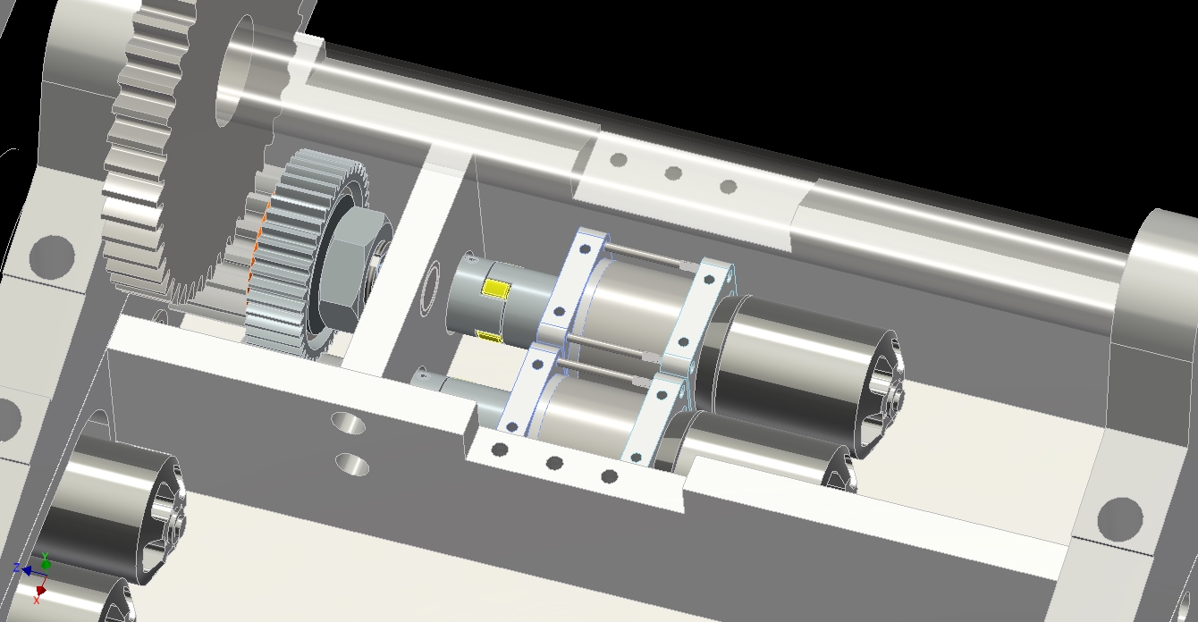
My pride and joy, the intermediate lift shaft, drops into place!

Adding lift motors and couplings now.

This is the “everything bracket” that was detailed in the Electronics buildout post. As it turned out, it was the longest piece ever done on a MarkForged machine! Because why else would you design something so ridiculously long!?  I printed one copy, then asked MarkForged to put a full set of spares on their print farm. The fiber backing here is kevlar.

Recall that I had to bail out to using the 160A DLUX controllers after finding out that the 250A model which I’d based my strategy around was no longer stocked. I redesigned the bracket in the electronics box to hold the 160A DLUX instead.

While other parts were coming together, the Mark Two was printing these parts out. Here, I’ve pulled the parts from the machine and am test fitting them to the waterjet-cut polycarbonate (Lexan) electronics casing. Paige and Cynthia took care of most of this waterjet-babysitting offsite.

The previous drivetrain test assembly was just wheels, nothing else. The final assembly meant hooking up chains! I bought a big box of #35H chain with the intent of making several swappable spare chains as we measured and cut each type. Four chains run the drivetrain per side, with three distinct lengths. There’s the center-to-front chain, the longest. Then the middle and rear chains were the same length, and finally the shortest one that bridges the two motors.

After this madness, it was time to start making the remaining details. Remember the nylon logs from the beginning? They were reduced to smaller nylon round things! I will point out that this material is quite possibly the most irritating substance I’ve ever had to machine. Short of hand-ground and sharpened high-speed steel tools, it would not really cut so much as smush annoyingly out of the way, making a large ring of deposited material in the way of your cut. However, I can’t fault it too much, as the parts were dimensionally accurate.

Other parts that were made in the same sitting included modifying the ball screws for the lift actuators, as well as the main lift shaft endcaps…

…which Shunk quickly attached to the ends of the lift shaft tube. This is 4140 steel endcaps on a 4130 steel tube with 1/8″ walls.

The big engine head studs were installed into the lift hub and the upper clamp hub checked for fit. It’s basically time for the arms to go on now…

In the next episode, the mad rush to the finish and the outlook at the event! I want to clear that early next week, such that once Overhaul’s match with Cobalt airs, I can post the fight analysis, ala Chaos Corps.

The Overhaul 2 Design & Build Series, Part 10: What Do You Mean It’s Out of Stock?

Previously, on How to Build an Overhaul…

dramatic over the shoulder camera angle here

charles stares intently at a lathe on autofeed

 –
CHARLES

“this insert seems a little dull and i want some mountain dew”

Machining the parts for the lift clutch was well under way by early March, and parts were coming in almost daily. Our goal was still to have “the robot minus the frame” done by the 3rd week of March, when the CNC machined frame was to arrive. For instance, here are infinite wheels:

After confirming that one hub works, it was time to make all of them. Now, these Colson wheels are made of polypropylene with overmolded rubber. The plastic is so soft that it would rather mush around than be cut, unless it had no other choice. Broaching the wheels made all kinds of neat Colson art, like so…

The next step to assemble all the drive wheels was to chamfer the tips of the waterjet-cut sprockets. Chamfering the tips makes the sprocket more tolerant to side-to-side chain slop since the teeth become narrower, and so the chain has more wiggle room before it tries to catch between teeth and fall off. And I can think of no better application where your chain is likely to have a sudden amount of side to side slop!

There were 30-something sprockets to machine, and I needed a solution to make life simple.

Enter MarkForged

I designed a jig that the sprockets bolted into – they had the correct center bore and two keyways to drive the sprockets, and were made using several layers of Kevlar reinforcement for strength (This wasn’t a critical application that had to be Kevlar – it was honestly what I just had loaded in the machine at the time. Any of their fibers would have been as rigid, or more rigid). On the inside of this print was a hex socket that fit a 1/2″-20 nut. A 1/2″-20 bolt runs through the body, giving it even more rigidity, as well as retaining the sprocket. It was then easy to chuck the jig into a lathe, holding the sprocket away from the chuck, and quickly chamfer both sides with a cutter. Then simply swap the sprocket out and continue!

The other piece shown is a portion of the electrical deck. It holds the robot-side main battery connector onto the electrical box, and was included with this print because why not. I wanted to try out the dimensions in real life to see if any adjustments had to be made.

After broaching the 5″ and 3″ colsons, I began to become concerned about how easy the wheels were to broach.  While the 5″ Colsons had plenty of material at the hub, the smaller 3″ ones had a significant portion of the hub’s radial thickness removed when I broached them. This was concerning, because the reduced material ring beyond the keyway, coupled with the sharp keyway edges, and the fact that the front wheels would be under the most stress when lifting an opponent, meant that the wheel was likely to crack apart.

Not cool. So one of the first “dynamic redesigns” of this build is now needed – the front wheels. I decided to design a MarkForged printable hub, to which a polyurethane tire is bonded.

The 3″ Colson wheel also only covers about half the hub width, as smaller sizes don’t come in the 2″ wide size. The new front wheel would be equally wide as the rest.

The outer ridges are to increase the surface area available for the eventual glue bond.

Here are some “cheat code” features to optimize the part for a MarkForged machine. Right now (as of 6/2016), their slicing software doesn’t yet allow you to prioritize “internal” features, such as holes or bores. All fiber lay is from the outermost perimeter inwards. The reasons for this are many (including feature recognition challenges), but bottom line is, I can’t tell the slicer to fiber up the keyed bore itself.

So in a manner similar to the “hairline split holes” method of 3d printing parts with more perimeters, I added a few Slots of Persuasion to forcefully route the fiber layers into the places where I need it – the keyway area. The fibers will handle the majority of the power transmission stress, so I was less worried about the plastic necking down here.

I also could have made the wheel a “C” shape, with the ends of the C so close together as to be almost touching – and in real life, the plastic would bond together anyhow – but I wanted to avoid having a single linear weak spot in an otherwise complete structural loop. So, little guidance slits won out here.

I then added a few Holes of Persuasion to force some fiber layers towards the outside layer, and some towards the inside of the hub surface.

Here is a finished wheel! See the keyway being surrounded by fiber, as are the inner and outer surfaces for the most part. I could have put Kevlar into all the layers, but decided to be a bit more economical. Each wheel contains just barely under half a spool of Kevlar. The rest of the volume is simply densely filled.

I’ll be the first to admit that I am not a master of composites and adhesives. I used whatever glue McMaster called “urethane glue”, part number 7493A21. My criterion for selecting this adhesive was “Says Urethane on it, does not require an expensive-ass dispensing gun or carefully pushing out with a stick, and comes in the little cute bubble packet”. This is roughly the same process used to select a bearing grease for Mikuvan’s front wheel bearings (“Well, it has a picture of a car on it”) and those haven’t blown up on me…. yet.

Help me.

The tire material is a soft urethane tube, McMaster part number 87235K74. I cut rings off the long tube I purchased, 2″ wide to accommodate the hubs. It gets stretched over the hub after the hub is throughly coated in the urethane OH GOD IT DOESN’T COME OFF AND IT’S STUCK TO EVERYTHING adhesive. I wiggle the tire on and use the dribbles to fill gaps and create edge fillets. Then I leave the wheels alone for a day or two.

The evening I put these together shall forever be remembered as Urethanocalypse 2016.

Here’s a pile of infinite finished wheels! Well, semi-infinite. We decided that a 100% set of spares was sufficient to start. In the event of post-match damage, swap the wheel for a known good one right away, then deal with the repairs after

Next up, infinite spider couplings. Notice how there’s a lot of “infinite” on this bot? Again, a manifestation of the design goal that is making all of the spare parts in one shot, with the parts themselves designed to be easily replicable. Other builders prefer building 1.0 robots first, then working on spare parts.

All of the spider couplings are broached for 1/8″ keyways to slide directly on the lift motors.

And finally, we get to….

Infinite SK3 motors.

This is where I introduce Equals Zero Robotics’ 2nd sponsor for the 2016 BattleBots season…

HOBBYKING!

Yes, that HobbyKing, a familiar sight on this website for many years!  I was in talks with them as early as Sadbot running on the dlux 250 hacks. Originally, it was just for more dlux 250 units, but I decided to go deeper. The robot community has a love-hate-love-again relationship with HobbyKing’s legendary Chinesium offerings, and many smaller bots have used HK parts to great effect. But can they play bigger?

Either way, some great exposure potential for HK, so they agreed to send goodies my way. One of these shipments was a nontrivial percentage of the world’s supply of SK3-6374-192 motors.

Another shipment was more running gear for the bot:


Critical subssystems and support equipment, all sponsored by HobbyKing.

Overhaul 2 will be running the 9XR Pro radio system with the long-range 433mhz R/C gear, to get me off the 2.4Ghz band. I wanted out of 2.4Ghz entirely – everything from other robots, to WiFi, to production running wireless lighting and microphones and the like, lives in 2.4Ghz. Last year, a few people had control difficulties (including yours truly) in the box, and I was not out to repeat that.

Next up are battery chargers and charger power supplies, as well as some BEC units to run the logic power (receivers, gaudy lighting, etc.) since the ESCs do not provide 5v power. Speaking of ESCs…

What’s missing is a boatload of DLUX 250 controllers.

Let’s rewind a few weeks here. What happened was that I compiled a bill of materials to send to Hobbyking, which included 12 dlux 250 controllers. Everything on the list was packed up and shipped to me, except the DLUX 250s, because…

I’ve gotten confirmation from the manager that this product has been completely discontinued and the factories are no longer making them.

Oh, snap.

After some highly intense back-and-forth over e-mail about possible replacements, I decided to spring for swapping the 250A model for the 160A model.

This was a very stressful decision. R/C amps are usually 0.2 to 0.5 of a real amp* and I was getting concerned about the real ampacity of these controllers. While I had familiarity with them from the BurnoutChibi project, the lack of large-package FETs (in favor of a sprinkling of small surface-mount FETs) and smaller thermal mass was the clincher. I also didn’t have a handle on their reliability – the only DLUX 250A units I’ve ever killed were due to my own stupidity, such as hard shorting outputs or leaving the bus capacitors off.

It was therefore imperative I get units in hand as soon as possible, as even the stock quantity of DLUX 160s was getting low (less than 15 remaining around the world in stock, as I recall). I really need to hand it to Hobbyking here for trying to round up stock in such short order.

*this statement is not backed by any form of science but is pretty accurate

The DLUX 160A controllers came a few days after the rest of the shipment. I immediate got cracking on tearing them open to see what I had to change for in the SimonK firmware. Luckily, the answer was not much. I had to redefine a few resistor values, and also set a correct deadtime (these switched slightly faster due to the smaller FET packages), but otherwise, they were the same pinout and layout. Go figure, but just to make sure.

I then uparmored them like I would the DLUX 250A, but these only had space for one big ol’ capacitor, which is better than nothing!

A set of three DLUX 160A controllers fully modded up. I was going to whip these things in Sadbot to ensure they don’t explode.

I removed the 250A controllers from Sadbot – now a valuable and rare commodity – and tied these guys in, then proceeded to drive around like a maniac, just like I did with the 250A, and lift & self right and do other things with the pokey stick.

Here’s a test video showing a little bit of it. The open floor tests were to try and stress the controller with many reversing and turning instances, and the sliding was induced by keeping the wheels spinning (drawing wheelspin current) as much as possible.

(RIP Frozen fans and normal people)

The controllers passed this test solidly, I’d say. I was beginning to smell SK3 windings before the controllers became too hot to touch, so that’s a good thing.

However, while powering up Sadbot for another test a few days later…

A minor smoke event occurred.

One issue with R/C controllers, especially large ones, is that they scale beyond their hardware designs that were originally put together for small ones. Without proper gate drive, and with the possibility of mixed parts in the power stage, if one FET blows up, it tends to start taking the rest with it. And some times, this happens almost spuriously. This is how a controller works for someone and not for the next person. Add to that the quality control generally associated with hobby parts, and….

Okay, let’s be clear: THERE IS NO SUCH THING AS A MINOR DLUX SMOKE EVENT. The whole thing is seemingly made of thermite, or the mix of materials acts as a rapid propellant, because it was over in 5 seconds, a foot of flame, and a huge plume of smoke. I was in fact fearful of a lithium fire with the batteries next to it, and was getting ready to shove the whole thing off the loading dock. The polycarbonate battery box from Overhaul 1 protected the batteries, luckily.

This was all that remained…. As you can see, the entire PCB is actually burnt in half.

By this time, I didn’t want to try to investigate yet another controller. And unless I were willing to pop out Brushless Rage™ in three weeks and get it right the first time, this is what I was going to have to deal with, and part of what I committed myself to doing – using big R/C parts in big robots – from the very start.

So it was time to put the controllers down and keep moving. I asked Hobbyking for a large stockpile of the 160A units to be laundered my way ASAP. I decided to formulate an electrical system continuity solution which used the DLUX 250As remaining (5) as much as possible, and substituting in the 160s if absolutely needed, but ensuring that I had a full bot set of DLUX 160A controllers right away.

While I was doing these tests, the others had finished machining the motor mounting blocks for the SK3s, and keying the shafts.

Ah, finally, all my ducks in a row!

The difference between a “left” motor and “right” motor is simply which direction the wire leads come out, to keep the wiring in the bot convenient.


The next step was to assemble all the gearboxes. Four left, four right, and four lift motors were to be assembled. Again, a 100% overhead (hehehe, overhead for Overhaul) such that we could pitch in a spare set right away and mull over the broken ones in the pits later.

Notice the delicious strawberry jelly on the left. Mmm, extreme-pressure additives.

Here’s a fully assembled drive motor, with retaining bracket!

Repeat like 20 billion times

Okay, so I lied about getting away from controllers, again!

Overhaul 2 still has that 1 brushed motor onboard, the A23-150 micro-Ampflow motor to run the clamping arm. To use this motor, I needed a high voltage (12S capable) DC motor controller.

Now, I had designed a 8S-capable motor controller of some type a little while ago, and in fact, one of the original RageBridge 2 plans was to have it be 12S-capable. But I decided to scale back for expense and usability reasons – most everyone runs these at 6S (around 24v) or in extreme, unsupported-by-manufacturer (AHEM, WILL BALES) cases, 10S (36-42v).

To change Rage over to the higher voltage specification was actually an intensive job, basically rebuilding the board. The main capacitors were changed to 50V types, the MOSFETs to 60v parts, and a lot of other little things moved along with them – such as changing the gate resistors to accommodate the new drive needs, and the logic regulator to a HV-rated part.

In the end, I whipped together two HVRage™ units for the clamp motor, and tested them (see the small blue wires used as scoping points) to ensure nothing was going to get TOO fiery.

And this is the conclusion of Overhaul 2: Actual Electric Boogaloo (sorry Orion). Next up? A Series of Tubes:

Side note: Overhaul 2 swag is now up on the BattleBots store, if you haven’t seen yet. All artwork by Cynthia! Proceeds of sales do go to the builders, so you’d be sponsoring supportng Overhaul for #season3!