The Overhaul 2018 Design and Build Series, Part 3: When Your Supply Chain is Missing a Half-Link

It’s fab time! The following story takes place in the last week of February to the first week of March – yep, that’s just over 3 weeks, reaching into 2 weeks, until the bot had to be in the crate! In fact, a lot of the earlier photos here were concurrent with finishing out the drivetrain changes and electronics module, since the mechanical modifications were first priority.

Alright, the first thing to do after two years of stagnation and one entire shop move is to take inventory. Some of Overhaul’s parts had wandered off into other projects or been repurposed, and others had been sold to needy builders elsewhere. Oh, and some things instead were to be deprecated and thrown out.

I was first out to ascertain how many good drive motors I had remaining. I originally built a whole bunch of spares and only ended up using two or three. But the lift motors at the time were low on stock at Hobbyking, so I only had four lift motors total – one of which was burnt out and the other had a severely damaged gearbox from (likely) the rumble and post-season shenanigans.

There were also other parts being counted – sprockets and drive hubs, and hardware relevant to the liftgear which I only had a few of to begin with.

By the end of the day, I had a good idea of what needed to be ordered from McMaster the following Monday, as well as what parts to ask HobbyKing for!


I began the stripping down of the bot during this process. Poor Overhaul – it’s mostly been living on a lift cart behind my work area, usually causing me to run into it in some way on a regular basis, causing a pattern of injuries on my leg which would have been highly suspicious during high school.

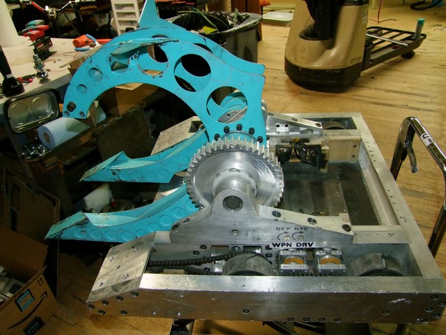
Breaking the bot down was important since I would want to start over with all new fasteners and ascertain the status of all of the parts, such as where a frame rail might need to get cleaned up or if this or that drive hub was about to let go anyway. There were also quite a few parts which were going to receive lightening in my efforts to make weight for DETHPLOW. Basically everything above in blue is being replaced completely, and a lot of parts which went into the now-previous design head will have to be deprecated.


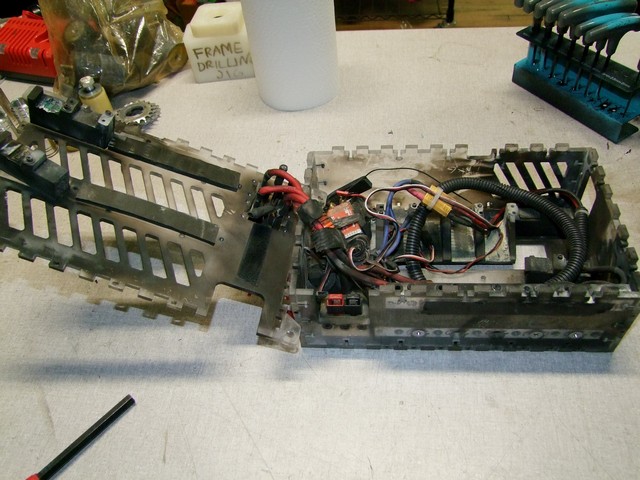
Ah, the sad electrical box. Overhaul hasn’t been operational since a year and a half ago when I sold the DLUX 250 reflashed ESCs to Ellis for Robot Wars. To my surprise, this damn thing still powered on. There is a single brushed RageBridge inside to run the former clamp motor, an A23-150 sized Ampflow motor, as well as a BEC module.

Oh well – everything which caught fire is considered automatically sketchy in my book, and this box had an entire unassembled spare if I somehow needed another one – so I salvaged the bus bars and some intact wiring harness parts and unceremoniously chucked the rest.

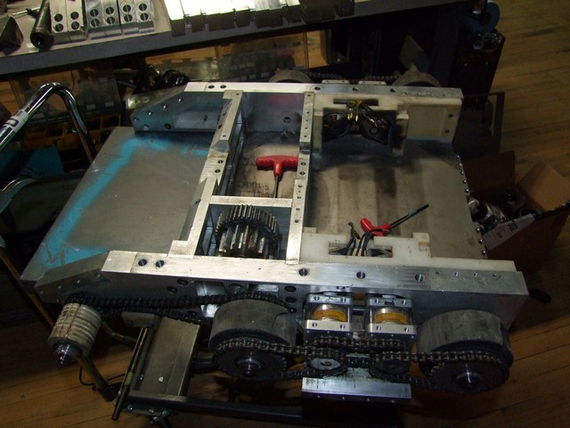
Overhaul is probably my current masterpiece in terms of design-for-assembly and design-for-service. I put more thought into how things go in and out into this bot than probably every other project I’ve ever made, combined. It’s actually very easy to knock down as one person, since the majority of the bot is supposed to be serviceable by 2 people in under 5 minutes. It takes on average only 2 minutes to release a set of drive motors and under 60 seconds to separate the upper and lower halves of the bot at the arm towers, after which the set of lift motors comes out with only 4 bolts.

The revisions will see some of this go away – for instance, the frame rail brace plate would add a dozen bolts and a different tool to the process. However, I was fine with this – at BattleBots with the current format, you usually have several hours of notice before fighting, if not days. It gets tighter around the playoffs and finals obviously, but the quickest turnaround I’ve witnessed was still on the order of 2-3 hours. If I was scrambling to replace frame rails that hard, it means I’m doing pretty damn well.

On the plus side, the actuator and upper clamp retainment strategies have been changed to be more easy to service.

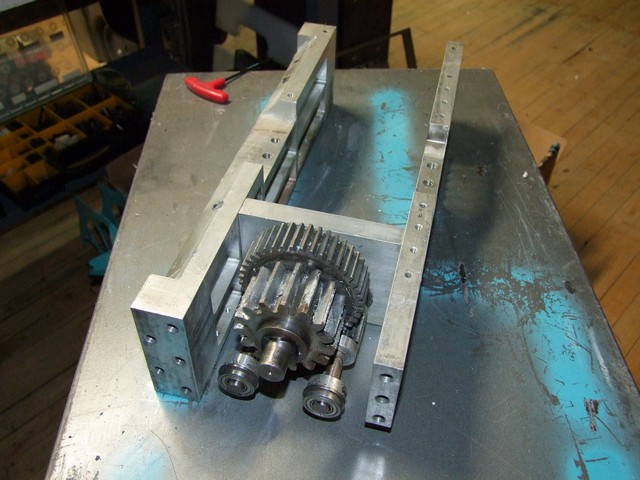
Well, when you get down to the basics, Overhaul is just a series of gears.


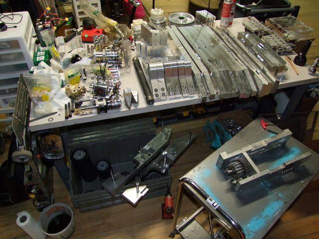
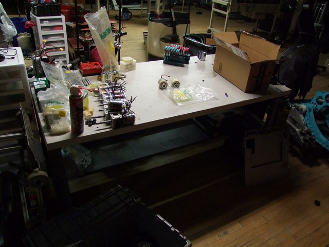
All said and done – this is what my table and bench area looks like. I sorted the remaining spare frame rails by type, since each type needed a different kind of surgery or modification.

Chibikart makes a cameo in this photo.

There was about 8 pounds to lose in the frame, spread across a few parts. Overhaul weighed in at 247.0 on the event scale during Season 2, so I used that as a cross-reference to the CAD weight of 240 pounds. To make sure DETHPLOW took me up to the same physical end weight in replacing the separate heavy wedges, and also taking into account the new frame brace plates, I had to get the bot down to around 230 pounds. The rest of the ‘missing weight’ was to be made up in the battery and ESC assembly being smaller and lighter.

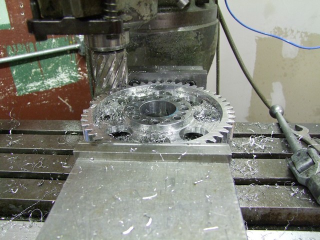
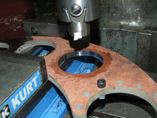
Above, I use an annular cutter (also some times called trepanning cutters) to empty out some of the interior of the Epic Lift Gear. If you’ve never used these before, they’re like specialized high-precision hole saws for metal, and can cut a large hole very cleanly and quickly. They used to be very expensive and specialized, but you can find Chinesium sets now that work fine for under $100.  This one was driven in low-gear on Bridget.

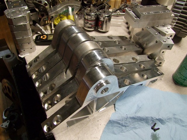
The arm towers themselves also lose a bit of meat, with each side getting 1/4″ removed. In a mild perversion of their use, I actually used the same 2″ diameter annular cutter to make the circular boss by simply leaving the interior portion and machining the rest away.

It was now the first week of March, and life suddenly got much more exciting.

I had been scouring the country for a more consistent source of the 4mm AR400 steel that makes up Overhaul’s clamp and fork profiles. Basically, the material seems to come and go at McMaster, who also seems to source it from the depths of a tropical rainforest as all of the AR grade steel I’ve ever gotten from them has been covered in rust and not a single one has really been straight.

Through a lot of calling around local steel companies, I was given an inside sales contact at SSAB – the international manufacturer of the UK/Europe robot fighting circle’s preferred armor steel, Hardox. The gist of the conversation was essentially “Hold on, what did you say you guys were building? Let me talk to the sales manager and we will see what we can do”.

Only afterwards did I do some research and found that SSAB was essentially the U.S. Steel of Sweden. To be fair, I’m not sure what I was expecting, since it’s not like some small mom-and-pop operation produces 8 million tons of high strength steel alloys a year.

So there we go – I’d like to formally welcome SSAB Americas as a sponsor of Overhaul this season! This explains the big Hardox logo on the Equals Zero Robotics Facebook page now.

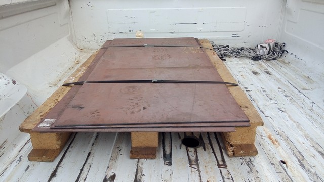
They not only straight up sent me a diced up 4′ x 8′ plate of 4mm Hardox 450, but also helped find a local steel distributor who had a fast-turnaround plasma cutting service for even more Hardox. This will come into play just a little later.

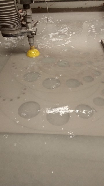
Alright, presented with several hundred pounds of steel, I will obviously go waterjet. I paid some hush money to the MIT Edgerton Center and popped out a few parts on the Omax 5555 in an evening. I started with 2 full “heads” for Overhaul and basically all of the kibbles which go into the new lift hub design, as well as one set of titanium brace plates.

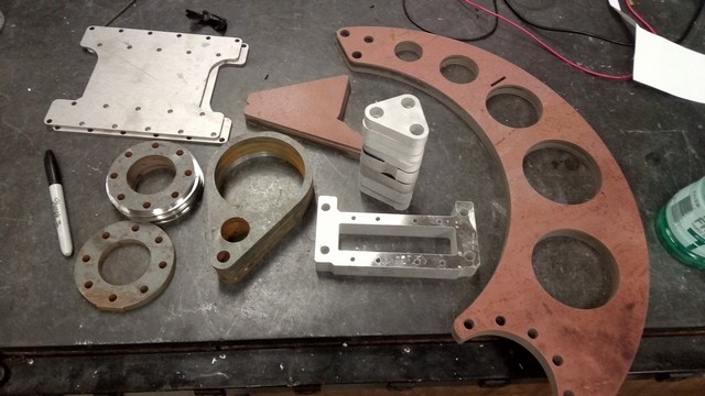
Here’s the finished parts in the middle of some post-machining.

Back at my shop, I cleaned up the actuator-mounting bore on the clamp side plates. The actuator trunions will ride directly in these holes, so I wanted a not-sandpaper finish here. I didn’t have a carbide boring bar that fit my old boring head, so I reground the old HSS lathe rool I used in there and just ran it very slowly and gently to scrape the little bit of Hardox off.

Harder steels might be horrifying to machine, but they do leave wonderful finishes if you know their weaknesses.

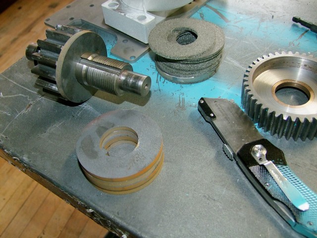
I made a design change to the lift clutch which entailed cutting out some new parts. I wanted to increase the clamping pressure significantly because Overhaul had a lot of trouble actually hauling stuff over during Season 2. To do this, I made new thicker pressure plates such that the tightening nut could exert a lot more force without causing bowing and decreasing of the contact area. I also switched to a higher-friction clutch material (what McMaster calls their high-coefficient of friction), from a medium one.

Additionally, I made over a half pound back here by machining down the Epic Lift Pinion and clutch gear! Technically, that shaft also never ever had to be made of steel – 7075 aluminum would have been highly reasonabel… but I already had slugs of steel sitting around in the right size back then…

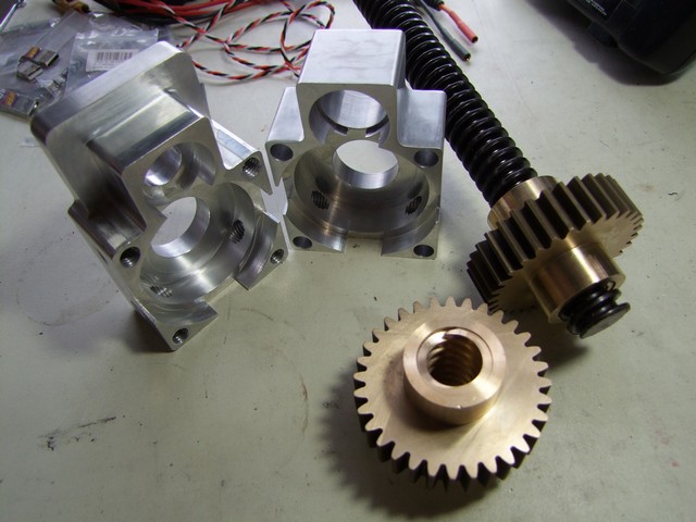
Just a couple of days later, the new actuator bodies arrived from my Chinese CM.

Oh. My. Baby robot Jesus.

Probably the most gorgeous assemblies I myself have ever designed and carried to fruition (if I do say so myself). The story of the gear-nut is a tragedy upon itself. I originally threw it at my Chinese shop along with the billet halves, expecting them to basically tell me to quit it with my English Acme thread in the middle of a gear nonsense.  I was fully expecting to just buy two bronze nuts and shove machined stock catalog gears around them.

The problem is then they asked me for a sample of the 1″-4 leadscrew, which is obviously not easy to get in China, as an assembly fitment. They already made one. What?

Absent the ability to mail a chunk of leadscrew (which I didn’t even order yet) in a timely fashion, we settled on the next best thing: I would send them a 3D model of the leadscrew, and they will SLA resin print it and use it as a fitment test. These gearnuts have less slop in the Acme thread than my Bridgeport does.

In the end, it was worth it! The gearnuts are probably the highlight of this whole operation – on almost every project and bot, I have something I call the “penising piece”, referencing the unfortunate tendency for us guys to put a lot of effort into something very showy and impractical for the sake of one-upping each other.

You know what I’m talking about. Don’t deny it. Think about what sport this is.

Too many parts and assemblies like that and your whole project becomes very out-of-scope quickly. Trust me on this, I used to do entire projects that way.

That is not industry terminology. Do not dare try to make it standardized.

There was only one “quality control” problem, and it wasn’t the Chinese’s fault. You see, the thrust bearings I specified on McMaster had a nominal outer diameter, which I designed the pocket for. It in fact was a full 0.02″ larger in real life.

I’m technically not even mad – it’s a thrust bearing. What kind of dumbass tries to make a radially tight-tolerenced fit on something like that?!

The outer shell of those bearings is just a stamped piece of steel – it doesn’t acually Bearing anything, it just vaguely holds the upper and lower races together so you don’t sprinkle the rollers everywhere.

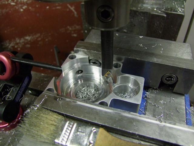
Sadly, I had to bore out my beautiful Chinesium to accommodate the ingrates.

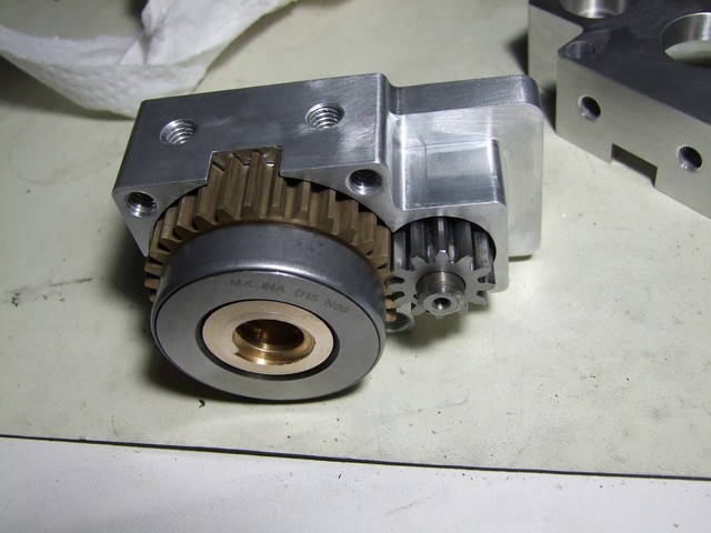
Here is how things fit together. The big thrust bearings sit directly on the face of the gear. The pinion shaft is retained via snap ring and has another bearing that carries it, located in the half not shown here.

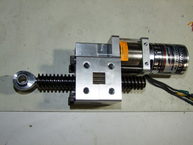
And this is how it fits together. I’m quite thrilled with this unit! It ended up weighing about 1lb less than the fiasco I designed last time around, is much smaller and also capable of much heavier loads due to the large trunnion diameter and thicker leadscrew.  The rod end is threaded into the leadscrew and retained with two cross-drilled 1/8″ roll pins each.

Next time on Overhaulin‘ – lots of welding. so much welding.
The Overhaul 2018 Design and Build Series, Part 2: Where Everything Gets Easier

Hey! There’s a robot-related TV show premiering on May 11th you might be interested in. There are robots on it, and they do stuff. They might even tell you about how the robots were made or about who made them! I might even be on it occasionally (But for sure not the first episode: The new format of the show was filmed in fairly cleanly episode-divided chunks, and I’m not quite at liberty to say which episode(s) Overhaul stars in)

Guess what? It’s finally after BattleBots. This means my life has finally returned to roughly normal (whatever that…. is), and most importantly, I can actually finish these damn build reports. Remember back in the day when this site was more hardcore, where I posted basically daily about what I made that day? It turns out “real life” is a class you can’t skip too many times a week. Build everything in college and ditch your classes, kids! I mean, uhh, be a responsible young adult and remain engaged in your education. Yeah. That’s the right message to send! Something something public facing role model…

We return to the design stage of Overhaul by picking up after the most imperative task – redoing the steel frontal parts of the bot – was finished. In fact, I left this post half-finished before I dove into making sure everything was done and had spares, etc.

Everything else honestly seemed easy by comparison, because I already determined what was going on with the other aspects of the bot beforehand, and it really only needed to be pounded through. The next two priorities after the new forks and clamp actuator were to finish designing the drive wheels so I could immediately start 3D printing cores and molds for production, and retrofitting the bot with Brushless Rages.


The wheel technology I wanted to use on the bot was pretty well developed by prototyping it with Überclocker last year for the Franklin and Motorama events. I essentially just scaled it up and kept the “scooter wheel” style molding features.


Something cool you can do with 3D printing easily is make fully interior voids that have no opening to the outside world. I didn’t want to waste material and time by printing a huge wheel which is mostly hollow anyway, and wanted more material perimeters near the highly-stressed hub area. But a fully spoked design would have been extra fragile in my mind.

Solution? I enclosed the spokes with endcaps that have 45-degree chamfered lead-ins so it can print without support. This way, I get the concentrated materal perimeter in the center and the outer regions, as well as two relatively solid endcaps. You can’t see these from the outside at all – they look like blank wheels.

The molds are constructed the exact same as Überclocker’s, too. I’m hurrying on the wheels first because I wanted to test the viability of the “twist to unlock” demolding strategy that I piloted with the smaller wheels. As you can see, I designed in giant wrench flats (or perhaps vising flats) so I can hold the mold in something. Up until this point, I was completely unsure if twist-to-unlock was even going to begin to work!

Parametric generation made designing the 3″ front wheels super easy! To really do parametric modeling well, you have to pay a lot of attention to the order that your features were made in. I’ve practiced using parametric-CAD for its actual parametric properties more in the past few years with consulting jobs, and Überclocker’s wheels were the first multi-variant parametric part of this complexity I’ve done and had gotten it to generate correctly on the first try. I haven’t even dared touch fully parametric assemblies.

The parameters were essentially related to wheel diameter/feature thicknesses, number of thru-slots, and suppression of the interior spokes of the larger one.

(Useful side note – the continuation of that article series about horizontal modeling is something that experienced CAD users all do subconsciously. I learned it the hard way through many of my models exploding, and watching friends with bad CAD habits having entire assemblies made of parts that are exploding. If you look back through how I generate Overhaul’s relatively complex wedge facets, that’s probably the best example I have visible of horizontal modeling concepts)

I imported the wheel assemblies and also added new 12-tooth drive sprockets. I’ve described many times how Overhaul was very under-geared with a design top speed of 18-19mph and could not use nearly all of its velocity space in the arena, coupled with limited traction (hopefully less an issue this time). My experiences with Clocker at Motorama with its new 10mph top speed showed that it felt a lot less squirrely and linear to drive despite not having the best traction.

Going to 12-tooth motor sprockets from the 15 tooth ones would bring that down to 14mph, which was historically a “sweet spot” speed for the 48ft BattleBox.

The liftgear remains pretty much the exact same as last time, but the gearboxes are now the BaneBots BB220 series. I got to test drive these in some of my recent consulting projects after talking with BaneBots post-Season 2. The problem with the P80s was the Double-D coupling inside starting to round off under high-torque loads. The BB220 shares a gear pitch with the P80s, so all my spare purchased gearsets are still useable, but have output stage carriers that are twice as thick and connected using a 12mm hex bore and not a 10mm DD.

I only had to design a different mounting plate to adapt these – the ratios are otherwise the same. BaneBots only sells 4:1 stages for this gearbox right now, but with the ring gear being the same gear pitch and tooth counts as the P80, you COULD fiddle a 3:1 stage anywhere but the output.

Next item on my agenda was the “Anti-Cobalting System” for the outer frame rails. I stewed pretty hard on how to implement these. The ideal solution would have been to box off the top and bottom of the rails with an intermediate tying member, or try to do it Clocker style with a thicker single spanning piece.

Problem is, there is a lot going on in that area – on one side, all the liftgear intermediate bearings are built into the frame rail, and the front drive chain also snakes around there. There’s also not much space to attach an upper brace plate on the inside frame rails without making it fully service-dependent on removing the arm towers (and hence the top half of the bot) for any kind of access to the drivetrain from the top.

I didn’t want to sacrifice that serviceability, and I was also much LESS concerned about “Cobalting” the rails save for a direct side hit because of DETHPLOW now tying both sides together with wubbie isolation. So the ACS became a single bridge plate which spanned the entire unsupported length between the center and front axles. I decided to make it from left over 4mm titanium stitched in through its entire length by 1/4-20 Grade 8 screws.

In a realistic direct hit to the frame side, that plate is still going to buckle and likely pop a few screws. Generally though, it takes transferring a relatively minusule amount of energy to the inner frame rail to prevent buckling. If I had more material and time, I would actually have made an entire width-of-bot bridging piece to act as a huge gusset for this whole area.

But I don’t! So here we are.

That’s actually….. it. There’s not much else going on in this bot which is substantially different this year. Electrically, though, it’s a different story. I decided to drastically refactor and simplify the electrical deck. Last season’s mantra was designing the E-deck and battery as two modules which are replaced wholesale in event of failure, then we figure out what’s wrong with the broken one later.

I really consider that system over-engineered now, and especially with DETHPLOW mode, I needed a lot of that weight back first. With the ESC choice being standardized, there wasn’t a need to make a whole rack of them removable at a time.

I also thought about the number of times I swapped a battery out to charge it and replaced it with a freshly charged one: 0

Every lithium battery worth using in a robot nowadays can charge at 2-5C rates. That means a full charge in 30 minutes or less, and matches at BattleBots will not occur that quickly. Overhaul is also not a bot which is so strenous on batteries that it will roll through an entire charge in one match – Overhaul 1 took up about half of is battery nominal capacity, and OH2 was even worse at like 1/3rd per match.

Therefore, I settled for keeping the Brushless Rages on a single plate accessible from the top for individual removal if needed, and batteries considered now non-removable and better armored within the bot.

So here’s what’s going on! My HobbyKing sponsorship was renewed around now, and they finally had the high C-rating Graphene packs in stock and ready to fire (heh) over to me. I was interested in these last season, but they had been very recently introduced then and the larger sizes were not yet in production.

I am not going to harp on the potential upsides and/or downsides of graphene battery marketing (bad sponsoree…. bad!), but 65C lipos are 65C lipos. Technically Overhaul would be just fine running 2 of them, but I had space for all 4.

The batteries form a single layer in the bot instead of being double-stacked near the back now.

A little hole-patterning later, and the new e-deck unit is basically done. The whole assembly is now wubbie-suspended within the bot, with the batteries (in real life) double-sided taped together into a brick and then sandwiched between the aluminum plate and a lower either-metal-or-Garolite plate, depending on available weight.

This is the assembly by itself. I found some space to squeeze in the 7th Brushless Rage to handle the clamp drive. This whole stack is around 3.5″ tall, so it leaves about 1/2 of air gap between the top plate and my ESCs. That miiiiiiiiiiiiiight be enough?

Seen in faint outline in the e-deck installation photo is a new top plate. I decided to do away with all the fancy cutouts and vents since the ESCs have a giant heat sink for a home. It will exist in two versions – a titanium 4mm one for DETHPLOW mode which trades about 3 pounds I can use, and one made of 4mm AR400/500 steel that weighs more for wedge fight mode (which is looking more and more like it’ll need ballasting)

Finally, the completing modification….. is moving the master switches to somewhere else that isn’t directly accessible on the top of the bot by wayward hammers. Hey, if someone reaches all the way back there (last season), we’re fucked anyway, right? Well guess what – someone did reach all the way there, and we were fucked.

The new location is accessible with the same tool, and with the activator still standing off to the side. The switches face 45-degrees upward directly under the arm tubes and sunk into the frame rail cubby – formerly occupied by Overhaul’s well-meaning but ineffective server fan exhaust port.

So here we go! The two master configurations for Overhaul this time:

General purpose match mode -wedge fights and vertical type weapons alike get the long arms and Limited Liability wedges, with exact positioning depending on who. The heavy top plate is in play. The configuration weight here is 230 pounds only, so I have a lot of wiggle room for silly accessories, minibots, and customized countermeasures.

The anti-KE DETHPLOW mode is specifically for horizontal bar and disc spinners. This mode is actually questionable against higher-hitting bar weapons like Icewave, but I’ve also not had to face such a thing yet, so hell if I know what happens!

And that’s it! The fabrication of everything obviously had to move quickly, so the build reports for Overhaul this year will be a little short. Stay tuned!