This post covers the reassembly work on the engine spanning roughly from mid June to before Dragon Con. After Dragon Con, my plan was to focus 100% on preparing Overhaul for the 2022 BattleBots season. The goal was to run the engine on a stand of some sort by then.

I cleaned up both of the heads using the (actually) brass wire brush seen previously and kept it from rusting again with some WD-40, since my work environment isn’t exactly weatherproof and by June, it’s very warm and moist.
I did this in part because of decisions about what to do with the head bolts. Recall one of my wants was to put some “stage one” and bulletproofing mods in while I’m reassembling. Well, the OEM head bolts on these engines were allegedly only 140ksi yield, or barely Grade 8. Could I verify this? Nah, but usually you would get a set of ARP heat-treated, rolled-thread studs with 220+ksi yield strength so you can really crank them down.
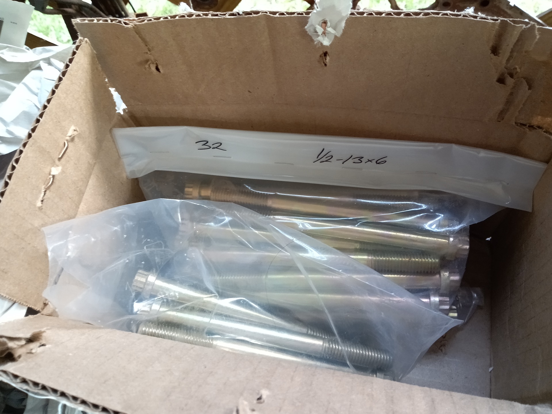
The problem was these were one trillion dollars (or so it felt with inflation and supply chain disruptions) and also terminally out of stock everywhere at the time, early-mid 2022.
I therefore went around scouting out where to get Grade 8, 9, or above 12-point cap screws – similar to the OEM head bolts, but just more hardcore. After all, I’m not running epic amounts of boost in the end, and if Snekvan survived on OEM head bolts, I was really only gaining long-term liability, which was preferred.
I found these Grade 9 equivalents on Specialty Fasteners (quite a name) and ordered up 35 – 17 per side plus one extra for the one I shear off.

While they were coming, I made an Internet Car Advice Recommended Upgrade to the heads. Legend has it when Ford/International went to the 7.3 liter size, they blocked off the coolant flow to the heads using plugs. Why? Who knows. Some allege for emissions purposes.
Whatever the case, lack of coolant flow through the heads makes them run hotter and potentially more prone to warping. A recommended hack appears to be punch (not drill) through the plugs on both ends of the head, enabling coolant passages in the block to connect once more.
I’m guessing you don’t drill because a punching process doesn’t generate metal shards everywhere inside these castings with their passageways and whatnot. Some people seem to remove these plugs outright, others leave a hole or two. I decided to go for the punch a hole approach.

The plot twist is of course you also have to drill holes in the head gaskets because they’re otherwise sealed off in this area.

And this is how I found myself drilling holes in brand new head gaskets. I just did a visual alignment and put a roughly 3/8″ sized hole here. Alright, Internet Car Advice… you better come through.

A good while ago, I bought a Ginormous Torque Wrench at a garage sale (at which I also obtained an arbor press). It went up to 250 ft-lbs and I had no idea what I could possibly tighten with it…. until now. Good thing I have it! The new head bolts were tightened in a few stages to 150 ft-lb.

With the heads reassembled, now I can bust out my poorly labeled bags from a few months prior and begin reassembly.

Here, the new Valve Pushy Roller Things are installed along with the pushrods.

I took the opportunity to make a modification to the “Bolt of Convenient Engine Mount Access” which would allow me to, if the event ever arose, to remove the engine mount on the driver’s side independently of the oil cooler.

I dropped what felt like an entire tube of silicone here on the intake manifold. In fact, this engine ended up having a full 4 or 5 tubes of silicone in various places. I think they really assume you buy the big cartridge of silicone or something, because I was used to the dainty “Make a 3mm wide bead” of Mikuvan’s instructions. Here, it seems more proper to just puke the silicone everywhere.

The intake manifold is now back on and secured.

Well, the distasteful modifications begin… Nobody will even get to see this in real life. But I will know it’s there.
(This was principally to prevent any surface rust on the valve covers from spreading, but I got carried away)

I’m moving onto putting the timing system back together now.

Yup, more extra painting for no reason. This is all going to get scratched and gouged up anyways as soon as I try hoisting the thing in.

The reattachment of the injection pump isn’t supposed to happen in this order, but I am deviating from “book steps” because I have a full reassembly going on where I can see the timing gears, not a repair job.

The IDI seems to have a very curious repair step where you have to play align-the-marks without being able to see them. Once the front cover is installed, you actually can’t see the Y-shaped timing mark because this camshaft gear is sunken below the top face of the block by about 2 inches.
The actual factory shop manual lists all kinds of shadetree sounding workarounds for pulling the injection pump gear, like scribing lines radially from the center to the matching Y stamping, or using dye on the teeth to line them up.
I took a more visceral approach and cut five little dimples into the tips of the two teeth next to the Y using a Dremel. These are concentrated at the very top face of the gear teeth, and therefore should not affect load carrying (famous last words). This way I can peer down from the top and see the reflections of the irregular cuts.

I’ve reattached the injection lines here too, along with a feeder line which will eventually feed into the rest of the fuel system. This was simply cut from the OEM filter-to-injection-pump line and flared a little bit to give a hose something to loop over and be clamped to (at the time, I didn’t own a proper bubble flaring or beading tool)

Injection pump dropped into place and fittings ready to attach!

This is what I mean by cheating when it comes to lining everything up. You’re supposed to have closed the front cover by now, which I haven’t, so I can fiddle the timing gear as much as I want. There is no visual on this gear mate if installed properly, and especially not in the van chassis.

With another what feels like whole tube of silicone, the front cover plate is mounted.
Not sure if I’m a fan of this design – this cover plate has bolts that do and don’t enter into the water jacket of the block (requiring silicone on bolt threads) and seals coolant passages adjacent to the crankcase which will be full of oil. With the water pump on the other side.
Seems like if I bung up any of these many silicone seals, I’m just asking for the big milkshake.

The oil cooler and the Bolt of Convenient Engine Mount Access are secured now. Of all the things I ran out of patience to paint…

This is one of the four Bolts of Milkshake Generation – the threads have to be siliconed, like a weird squishy Loctite, or you’ll pour pressurized coolant right into the crankcase.

Of course, I wouldn’t just do all of this without being extra.
So I basically have the entire thing reassembled up front at this point, except one demon from the beginning of the year which I now had to slay: The harmonic balancer which has a broken puller bolt remnant in it.

I set it up on the Benchmaster, Master of Benches and homed in on the hole with conical edge finders, then used a 7/16″ diameter cutter to create a mild counterbore as well as a flat bottom I could then drill into.

Here’s the prepared surface. I went down only as far as to fully turn the broken bolt into a flat surface. I still wanted to retain as much original thread here as I could.

Next, I dove in with a 5/16″ diameter drill bit. This just happens to the be the tap drill size for 3/8″-16 threads anyway. I somehow hit it so dead center that the entire bolt disintegrated into curls, and I could actually see the original threads intact.

Exciting times. I decided to chase the threads anyhow with a tap just to clear out all the debris.

Then I cleaned the part up and decided to be EXTRA again.

REALLY, REALLY EXTRA.

Like, goodness this is extra.

It’s a pity nobody will ever see this Miku-colored (and rust) engine.

Lastly, with the entire top and front side closed up, there was no longer a danger of dropping things downwards. So with another two tubes of silicone or so, the absolutely massive oil pan is closed up!

That same night, I went ahead and made the return lines.

The next task was to flip the engine around on the…
Wait, there’s no way to mount the engine using its front bolts. I’m going to have to do the rear cover plate and seal install with it hanging in midair, you say? Let’s do it!

There’s really only two things going on here, the rear cover plate (with seal) and the transmission adapter plate.

Getting closer to the end here with the flywheel and torque converter adapter plate now installed. Torquing these bolts with an engine hanging in midair was a unique experience.

With the flywheel mounted, the mounting ears of the Harbor Freight 2-ton stand were no longer long enough to reach the mounting plate. I had to supplement it with 1″ spacers as well as longer bolts; both were unceremoniously sourced from the hardware store right before they closed Saturday night. Also seen here is the oil pressure sensor, freshly installed on a riser coupler thing to clear the taller transmission mounting plate of the IDI. In Vantruck’s old 460, this thing sat in the same spot, but a lot lower.
So here we have it. It’s 2 weeks before Dragon Con in late August now, and I’m ready to fire this thing up. Stay tuned for THE TESTENING!